00193411-02.pdf - 第180页
7 Station extensions User Manual SIPLACE HS-60 7.9 Component s ensor Software version SR.503.xx 07/2003 US Edition 180 7.9.2 Measuring conditions The foll owing con ditions must be ful filled i n order to o btain a va li…
User Manual SIPLACE HS-60 7 Station extensions
Software version SR.503.xx 07/2003 US Edition 7.9 Component sensor
179
7
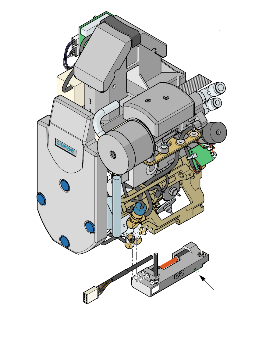
Fig. 7.9 - 2 Placement head with component sensor
7
The green control LED lights up if the component sensor is switched on and the invisible IR light
beam for the component height measurement (see Fig. 7.9 - 2
red strip) is not interrupted. You
can interrupt the IR beam to check that it is working correctly. The green LED must go out.
Green control LED
7 Station extensions User Manual SIPLACE HS-60
7.9 Component sensor Software version SR.503.xx 07/2003 US Edition
180
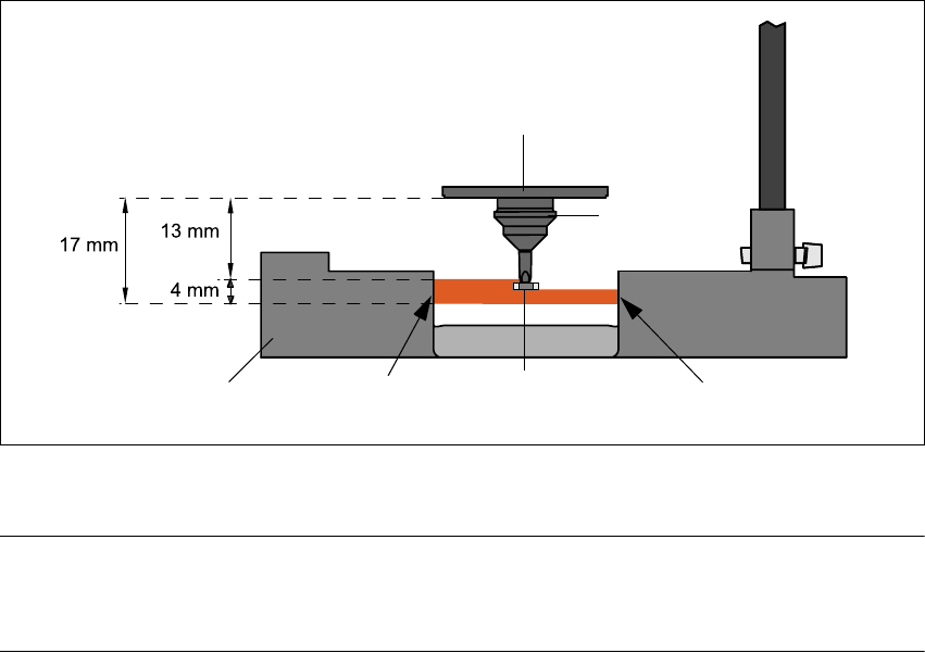
7.9.2 Measuring conditions
The following conditions must be fulfilled in order to obtain a valid measurement:
– The light beam must touch the empty nozzle tip during the calibration process.
– The nozzle tip must be inside the light beam when it is holding a component.
– Minimum nozzle length 13 mm
– Nozzle length + component height + tolerance < 17 mm
If these conditions are fulfilled, it is possible to determine whether a component is present or ab-
sent, or to measure the component height.
The minimum difference in height is 100 µm.
7
Fig. 7.9 - 3 Component sensor, working principle
7
PLEASE NOTE 7
If you are placing 0201 components with the 906 nozzle, it is essential to use the component sen-
sor since no vacuum measurements are possible. 7
Using the component sensor can also improve the dpm rate when placing other small compo-
nents, such as 0402 or 0603 components.
When selecting the component sensor from the package form list, note that the component can
only be placed on machines that are equipped with that component sensor.
Incremental disk
Component
Nozzle
IR LED PhototransistorCross-section through
component sensor
User Manual SIPLACE HS-60 7 Station extensions
Software version SR.503.xx 07/2003 US Edition 7.10 SIPLACE productivity lift
181
7.10 SIPLACE productivity lift
7.10.1 Concept of parallel placement
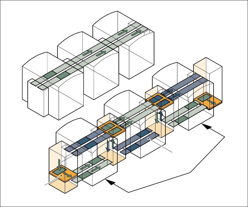
Placement lines are generally arranged in series and are linked to one another serially. The
placement program is processed sequentially while the PCBs are transported from one machine
to the next. This means that the placement of a PCB is distributed between various machines.
7
Fig. 7.10 - 1 A comparison of serial and parallel lines
When machines are connected in parallel, the components to be placed by individual machines
are combined. Several machines work through the same placement program. They place all the
components on one machine that would be distributed between several machines with serial pro-
cessing. When one machine runs out of capacity, the PCBs are moved to and placed at the next
machine with the same placement program. This combination of machines with the same com-
ponents to be placed is known as a group or “cluster”.
Serial line
Parallel line
Underfloor
conveyor
Group (cluster)
Horizontal/
vertical lift