00193411-02.pdf - 第64页
2 Operational safety User Manual SIPLACE HS-60 2.8 Energy state of the machine af ter switching off at the main power switch Sof tware version SR.503.xx 07/2003 US E dition 64 2.8.1 Placement system switched off at the m…
User Manual SIPLACE HS-60 2 Operational safety
Software version SR.503.xx 07/2003 US Edition 2.8 Energy state of the machine after switching off at the main power switch
63
2
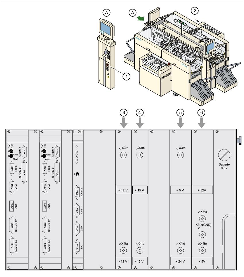
Fig. 2.8 - 2 Position of control unit and main power switch
2
(1) Main power switch
(2) Control unit
(3) Power supply unit ± 12 VDC
(4) Power supply unit ± 15 VDC
(5) Power supply unit + 5 VDC/+ 24 VDC
(6) Power supply unit + 5 VDC/+ 52 VDC
2 Operational safety User Manual SIPLACE HS-60
2.8 Energy state of the machine after switching off at the main power switch Software version SR.503.xx 07/2003 US Edition
64
2.8.1 Placement system switched off at the main power switch, but still connected ...
The following table specifies the voltages of modules when the automatic placement system is
switched off at the main switch, but still connected to the mains supply.
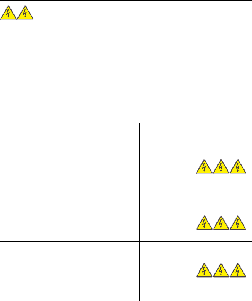
WARNING 2
The following components still carry potentially lethal voltages even if the main power switch is
switched off:
– Cable connection terminals 1, 3, and 5 of the S1 main power switch
– Mains filter Z1
– BU1 service socket
– F1 automatic circuit breaker for the service socket
– The color of all individual wires, which still carry potentially lethal voltages even if the main
power switch is switched off, is brown.
2
Module Voltage
Main power filter Z1
Terminals L1, L2, L3
3 x 204 VAC
3 x 230 VAC
3 x 380 VAC
3 x 400 VAC
3 x 415 VAC
BU1 service socket
115 VAC
130 VAC
220 VAC
230 VAC
240 VAC
F1 automatic circuit breaker
115 VAC
130 VAC
220 VAC
230 VAC
240 VAC
User Manual SIPLACE HS-60 2 Operational safety
Software version SR.503.xx 07/2003 US Edition 2.8 Energy state of the machine after switching off at the main power switch
65
2
2.8.2 Placement system switched off at the main power switch and disconnected ...
The automatic placement system is unpowered, apart from slight residual voltages in the servo
unit.
2.8.3 Compressed air conditions in the machine after switching off at the main
power switch
When the system is switched off at the main power switch (item 1 in Fig. 2.8 - 1) or if the power
supply fails, the electrically-controlled main valve Y1 of the compressed air unit closes (item 3 in
Fig. 2.8 - 1
, page ). The pressure will drop to 0 MPa (0 bar) within 5 seconds.
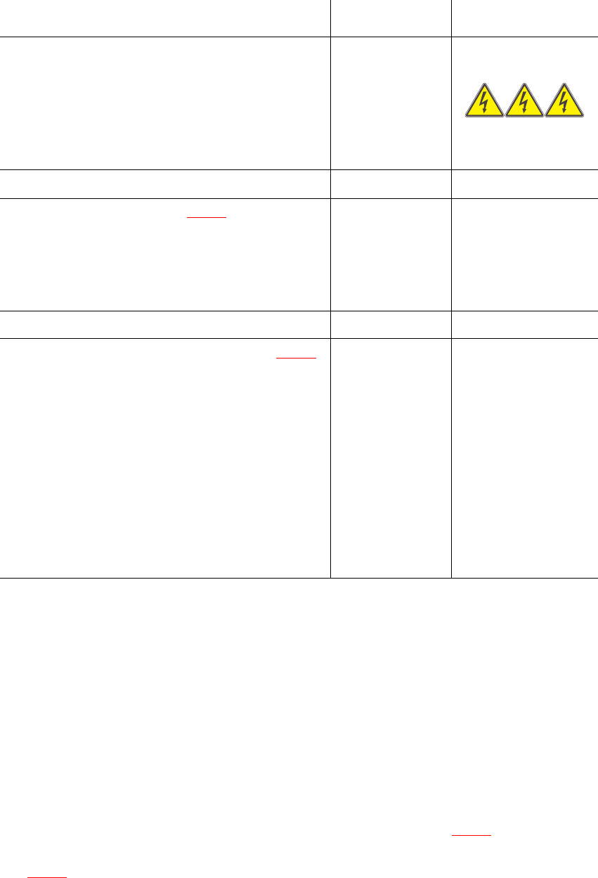
S1 main power switch
Terminals 1, 3, 5 3 x 204 VAC
3 x 230 VAC
3 x 380 VAC
3 x 400 VAC
3 x 415 VAC
Servo unit (see item 5 in Fig. 2.8 - 2
)
Test socket X2
Test socket X3
Test socket X4
GND X1
< 10 VDC
< 10 VDC
< 10 VDC
Control unit (see items 3, 4, 5, and 6 in Fig. 2.8 - 2
)
Test socket + 12 VDC (x3ta)
Test socket 12 VDC (x4ta)
Test socket + 15 VDC (x3tb)
Test socket -15 VDC (x4tb)
Test socket + 5 VDC (x3td)
Test socket + 24 VDC (x4td)
Test socket + 52 VDC (x5te)
Test socket + 5 VDC (x4te)
GND (x3td)
0 VDC
0 VDC
0 VDC
0 VDC
0 VDC
0 VDC
0 VDC
0 VDC
Module Voltage