00193411-02.pdf - 第124页
5 Operator, Line engineer, Service engineer User M anual SIPLACE HS -60 5.10 Operating status indicator lamp Sof tware version SR.503.xx07/ 2003 US Edition 124 5.10 Operating s t atus indica tor lamp The ind icator lam p…
User Manual SIPLACE HS-60 5 Operator, Line engineer, Service engineer
Software version SR.503.xx 07/2003 US Edition 5.9 Component trolley
123
5.9.3 Docking in the component trolley
WARNING 5
Check that the placement head is outside the range of the component trolley.
CAUTION 5
When docking the component trolley, ensure that the table bed is in its top end position and the
bracket (item 5) is folded up.
Æ Cut off the empty tapes for the feeders.
Æ Make sure that the contact surface (item 9) for the component table bed is clean.
Æ CAREFULLY push the component trolley into the placement system.
Æ Plug the connecting cable of the component trolley into the socket (item 2) on the machine.
Æ Open the cover over the push-button used to raise and lower the component feeder table bed.
Æ Hold down the button (item 1) until the component table bed reaches its top end position.
Æ Check that the centering holes in the component table bed lie precisely over the centering pins
of the placement system.
WARNING DANGER OF CRUSHING 5
When lowering the component table bed, never reach into the gap between the feeders and
the used tape channel. 5
Æ Pull the two actuating tubes (item 6) towards you at the same time and then lower the trolley
bracket (item 5) in order to be able to lower the component table bed.
Æ Ensure that the centering pins engage in the centering holes in the component table bed and
that the component table bed is fully lowered.
Æ Close the cover over the push-button (item 1).
Æ Close the protective cover.
Æ Press the Start button to start the placement system.
5 Operator, Line engineer, Service engineer User Manual SIPLACE HS-60
5.10 Operating status indicator lamp Software version SR.503.xx07/2003 US Edition
124
5.10 Operating status indicator lamp
The indicator lamp is used to signal operating statuses and malfunctions of the placement system.
5.10.1 Description of the functions
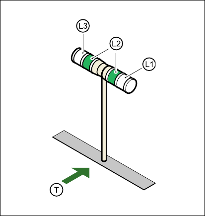
Fig. 5.10 - 1 Operating status indicator lamp
L1 Fault indicator lamp (white, right)
L2 Operating status lamp (green, both lamps switched in parallel)
L3 Fault indicator lamp (white, left)
T Direction of PCB transport
5.10.2 General operating statuses
– Operating status lamp (green) on continuously
The placement system is in service.
– Operating status lamp (green) flashes
The placement system is waiting for a PCB on the input belt or the placement system is waiting
until the output belt is free.
– Right white fault indicator lamp L1 flashes
One or more tracks are empty on the right-hand side of the placement system. The placement
system continues to place any remaining components.

User Manual SIPLACE HS-60 5 Operator, Line engineer, Service engineer
Software version SR.503.xx 07/2003 US Edition 5.10 Operating status indicator lamp
125
– Left white fault indicator lamp L3 flashes
One or more tracks are empty on the left-hand side of the placement system. The placement
system continues to place any remaining components.
– Right white fault indicator lamp (L1) on continuously - green operating status lamp (L2) off
An error has occurred on the right-hand side of the placement system -> the placement system
has stopped.
– Left white fault indicator lamp (L1) on continuously - green operating status lamp (L2) off
An error has occurred on the left-hand side of the placement system -> the placement system
has stopped.
– Both white fault indicator lamps (L1 and L3) on continuously - green operating status lamp off
An error has occurred that affects the entire placement system -> the placement system has
stopped.
5.10.3 Programmed operating status displays
The following table shows the programmed operating status displays in the standard configuration
(version as supplied) and lists their meaning on the individual lamps of the main fault indicator.
The entries in the table next to "flashes" refer to the frequency with which the relevant lamp flashes
for a given event. The entry (1, 5), for example, can be explained as follows:
– The first number in the brackets indicates the time, expressed in 100 msec intervals, for which
the fault indicator lamp is switched on, i.e. 1 x 100 msec in the above example.
– The second number in the brackets indicates the time, expressed in 100 msec intervals, for
which the fault indicator lamp is switched off, i.e. 5 x 100 msec in the above example.
5
L1 (white)
(right lamp)
L2 (green) L3 (white)
(left lamp)
Meaning
Status display
flashes (1,10) flashes (7,7) flashes (1,10) Reference run
unchanged flashes (1,5) unchanged Waiting until axes in position
unchanged flashes (7,7) unchanged Waiting for setup data
unchanged flashes (7,7) unchanged Waiting for cluster data
unchanged flashes (7,7) unchanged Load table program
unchanged flashes (7,7) unchanged Position detection
unchanged flashes (1,10) unchanged Bad fiducial detection
unchanged flashes (7,7) unchanged Nozzle configuration test
unchanged flashes (7,7) unchanged Feeder position detection
unchanged flashes (7,7) unchanged One track is empty