00193411-02.pdf - 第13页
User Manual SIPLAC E HS-60 1 Introduction Software version SR.503.xx 07/2003 US Edition 13 1 Introduction These o perating instructi ons pro vide a ma nual or ref erence wo rk for – operati ng and – setting up the HS-60 …
Index of Figures User Manual SIPLACE HS-60
07/2003 US Edition
12
Fig. 5.7 - 1 Pick-up position for components > 3 mm and </= 3 mm. . . . . . . . . . . . . . . . . . . . . . . . . 117
Fig. 5.7 - 2 Position of the component and its pick-up angle . . . . . . . . . . . . . . . . . . . . . . . . . . . . . . . 118
Fig. 5.9 - 1 Safety instructions on the component trolley . . . . . . . . . . . . . . . . . . . . . . . . . . . . . . . . . . 120
Fig. 5.9 - 2 Docking or undocking the component trolley . . . . . . . . . . . . . . . . . . . . . . . . . . . . . . . . . . 121
Fig. 5.10 - 1 Operating status indicator lamp . . . . . . . . . . . . . . . . . . . . . . . . . . . . . . . . . . . . . . . . . . . . 124
Fig. 6.2 - 1 8 mm S II feeder. . . . . . . . . . . . . . . . . . . . . . . . . . . . . . . . . . . . . . . . . . . . . . . . . . . . . . . . 129
Fig. 6.2 - 2 3 x 8 mm S feeder . . . . . . . . . . . . . . . . . . . . . . . . . . . . . . . . . . . . . . . . . . . . . . . . . . . . . . 130
Fig. 6.2 - 3 3 x 8 mm S feeder for 0201/0402 components. . . . . . . . . . . . . . . . . . . . . . . . . . . . . . . . . 131
Fig. 6.2 - 4 12/16 mm S feeder. . . . . . . . . . . . . . . . . . . . . . . . . . . . . . . . . . . . . . . . . . . . . . . . . . . . . . 132
Fig. 6.2 - 5 12 mm S feeder for capacitors based on powdered metal, model C/D . . . . . . . . . . . . . . 133
Fig. 6.2 - 6 12 mm S feeder for capacitors based on powdered metal, model E . . . . . . . . . . . . . . . . 134
Fig. 6.2 - 7 24/32 mm S feeder. . . . . . . . . . . . . . . . . . . . . . . . . . . . . . . . . . . . . . . . . . . . . . . . . . . . . . 135
Fig. 6.2 - 8 Bulk case feeder. . . . . . . . . . . . . . . . . . . . . . . . . . . . . . . . . . . . . . . . . . . . . . . . . . . . . . . . 136
Fig. 6.3 - 1 Inserting 30 or 45 mm wide feeders on the component feeder table . . . . . . . . . . . . . . . . 138
Fig. 6.4 - 1 Component trolley. . . . . . . . . . . . . . . . . . . . . . . . . . . . . . . . . . . . . . . . . . . . . . . . . . . . . . . 139
Fig. 6.4 - 2 Component trolley with tape container . . . . . . . . . . . . . . . . . . . . . . . . . . . . . . . . . . . . . . . 140
Fig. 6.4 - 3 Compressed air supply for bulk case feeders. . . . . . . . . . . . . . . . . . . . . . . . . . . . . . . . . . 142
Fig. 6.4 - 4 Support for the middle tape reel for 3 x 8 mm feeders . . . . . . . . . . . . . . . . . . . . . . . . . . . 143
Fig. 6.5 - 1 Position of the used tape cutter . . . . . . . . . . . . . . . . . . . . . . . . . . . . . . . . . . . . . . . . . . . . 144
Fig. 6.5 - 2 Used tape cutter . . . . . . . . . . . . . . . . . . . . . . . . . . . . . . . . . . . . . . . . . . . . . . . . . . . . . . . . 145
Fig. 6.5 - 3 Used tape guide in cutter . . . . . . . . . . . . . . . . . . . . . . . . . . . . . . . . . . . . . . . . . . . . . . . . . 146
Fig. 6.5 - 4 Pull-out waste tape container in the component trolley . . . . . . . . . . . . . . . . . . . . . . . . . . 147
Fig. 7.1 - 1 Position of the nozzle changer . . . . . . . . . . . . . . . . . . . . . . . . . . . . . . . . . . . . . . . . . . . . . 150
Fig. 7.1 - 2 Magazine and nozzle garages . . . . . . . . . . . . . . . . . . . . . . . . . . . . . . . . . . . . . . . . . . . . . 152
Fig. 7.1 - 3 Changing the magazine . . . . . . . . . . . . . . . . . . . . . . . . . . . . . . . . . . . . . . . . . . . . . . . . . . 154
Fig. 7.1 - 4 Nozzle changer - position detection . . . . . . . . . . . . . . . . . . . . . . . . . . . . . . . . . . . . . . . . . 155
Fig. 7.2 - 1 Component barcode reader . . . . . . . . . . . . . . . . . . . . . . . . . . . . . . . . . . . . . . . . . . . . . . . 156
Fig. 7.3 - 1 Structure of the dual conveyor . . . . . . . . . . . . . . . . . . . . . . . . . . . . . . . . . . . . . . . . . . . . . 158
Fig. 7.4 - 1 PCB barcode block diagram. . . . . . . . . . . . . . . . . . . . . . . . . . . . . . . . . . . . . . . . . . . . . . . 162
Fig. 7.4 - 2 PCB barcode reading head, profiled rails for PCB barcode reader ’bottom’/’top’. . . . . . . 163
Fig. 7.4 - 3 Assembly options for the PCB barcode reader. . . . . . . . . . . . . . . . . . . . . . . . . . . . . . . . . 166
Fig. 7.5 - 1 Structure of the ceramic substrate centering unit. . . . . . . . . . . . . . . . . . . . . . . . . . . . . . . 168
Fig. 7.5 - 2 Recommended fiducial shape . . . . . . . . . . . . . . . . . . . . . . . . . . . . . . . . . . . . . . . . . . . . . 169
Fig. 7.5 - 3 Multi-color PCB camera . . . . . . . . . . . . . . . . . . . . . . . . . . . . . . . . . . . . . . . . . . . . . . . . . . 171
Fig. 7.6 - 1 Fine calibration principle. . . . . . . . . . . . . . . . . . . . . . . . . . . . . . . . . . . . . . . . . . . . . . . . . . 174
Fig. 7.7 - 1 DCA camera on the 12-segment Collect&Place head . . . . . . . . . . . . . . . . . . . . . . . . . . . 175
Fig. 7.8 - 1 DCA camera. . . . . . . . . . . . . . . . . . . . . . . . . . . . . . . . . . . . . . . . . . . . . . . . . . . . . . . . . . . 177
Fig. 7.9 - 1 Component sensor . . . . . . . . . . . . . . . . . . . . . . . . . . . . . . . . . . . . . . . . . . . . . . . . . . . . . . 178
Fig. 7.9 - 2 Placement head with component sensor . . . . . . . . . . . . . . . . . . . . . . . . . . . . . . . . . . . . . 179
Fig. 7.9 - 3 Component sensor, working principle. . . . . . . . . . . . . . . . . . . . . . . . . . . . . . . . . . . . . . . . 180
Fig. 7.10 - 1 A comparison of serial and parallel lines . . . . . . . . . . . . . . . . . . . . . . . . . . . . . . . . . . . . . 181
Fig. 7.10 - 2 Horizontal / vertical shuttle (HV shuttle), conveyor track change and lift function . . . . . . 182
Fig. 7.10 - 3 Productivity lift – avoiding stoppages . . . . . . . . . . . . . . . . . . . . . . . . . . . . . . . . . . . . . . . . 183
User Manual SIPLACE HS-60 1 Introduction
Software version SR.503.xx 07/2003 US Edition
13
1 Introduction
These operating instructions provide a manual or reference work for
– operating and
– setting up
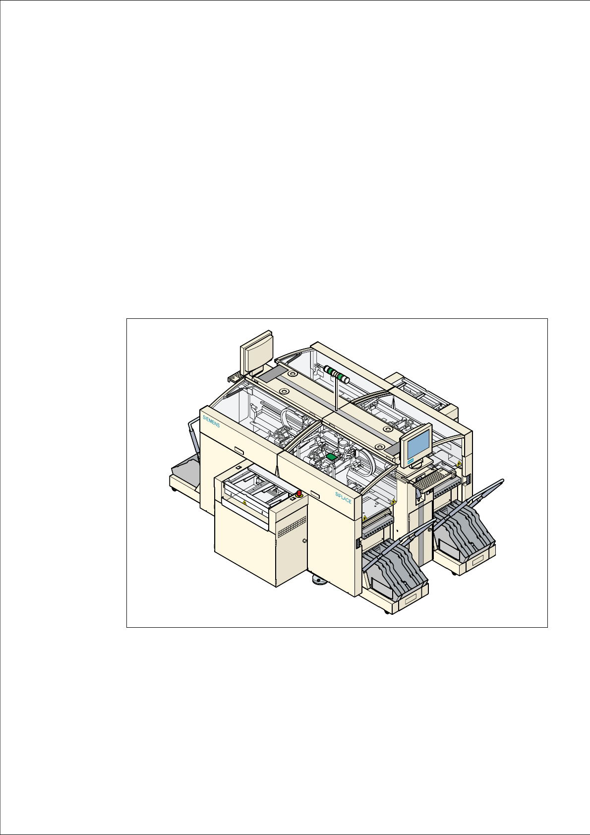
the HS-60 placement system.
The header of each chapter contains the
– release and
– software version
to which this manual applies. 1
1
Fig. 1.0 - 1 SIPLACE HS-60 placement system
1 Introduction User Manual SIPLACE HS-60
1.1 General Software version SR.503.xx 07/2003 US Edition
14
1.1 General
1.1.1 How to get information
If you have any further questions concerning this manual or if you would like additional information
on a particular topic, please get in touch with your local SIEMENSDEMATIC dealer or contact us
directly at:
SIEMENSDEMATIC AG
Rupert-Mayer-Str. 44
D-81359 München 1
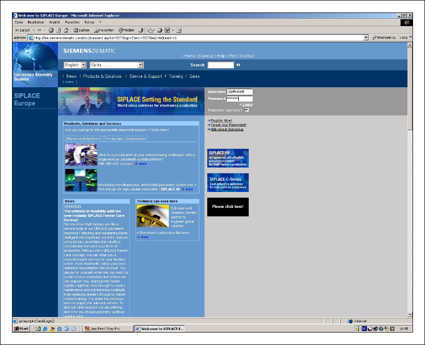
1.1.2 SIPLACE on the World Wide Web (WWW)
We also have our own site on the Internet. Why not log onto our SIPLACE home page at http://
www.siplace.com?
1
Fig. 1.1 - 1 The SIPLACE home page