00193411-02.pdf - 第87页
User Manual SIPLAC E HS-60 3 Technical data Software version SR.503.xx 07/2003 US Edition 3.7 Overview of the modules - gantries 87 3.7.2 Structure of the X axis 3 Fig. 3.7 - 2 Str ucture of t he X axis The X axis essent…
3 Technical data User Manual SIPLACE HS-60
3.7 Overview of the modules - gantries Software version SR.503.xx 07/2003 US Edition
86
3.7 Overview of the modules - gantries
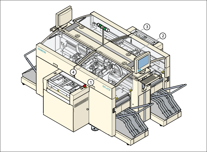
3.7.1 Position of the gantries
3
Fig. 3.7 - 1 Position of the gantries
3
(1) Gantry 1 (sector 1)
(2) Gantry 2 (sector 2)
(3) Gantry 3 (sector 3)
(4) Gantry 4 (sector 4)
The gantry system consists of two functional groups
– X axis and
–Y axis
User Manual SIPLACE HS-60 3 Technical data
Software version SR.503.xx 07/2003 US Edition 3.7 Overview of the modules - gantries
87
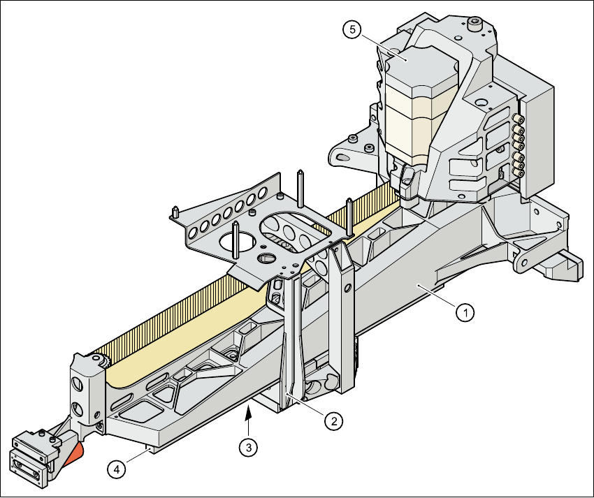
3.7.2 Structure of the X axis
3
Fig. 3.7 - 2 Structure of the X axis
The X axis essentially consists of the following main modules:
– Gantry arm (1)
– Head mount (2)
– Linear measuring system (3)
– X axis guide system (4)
– X axis three-phase AC servomotor (5)
The head mount holds the following components
– Sub-gantry camera (camera for the PCB vision module)
– Head board
– Measuring head for the X axis measuring system
– Collect&Place head
3 Technical data User Manual SIPLACE HS-60
3.7 Overview of the modules - gantries Software version SR.503.xx 07/2003 US Edition
88
3.7.3 Technical data for the X axis
3
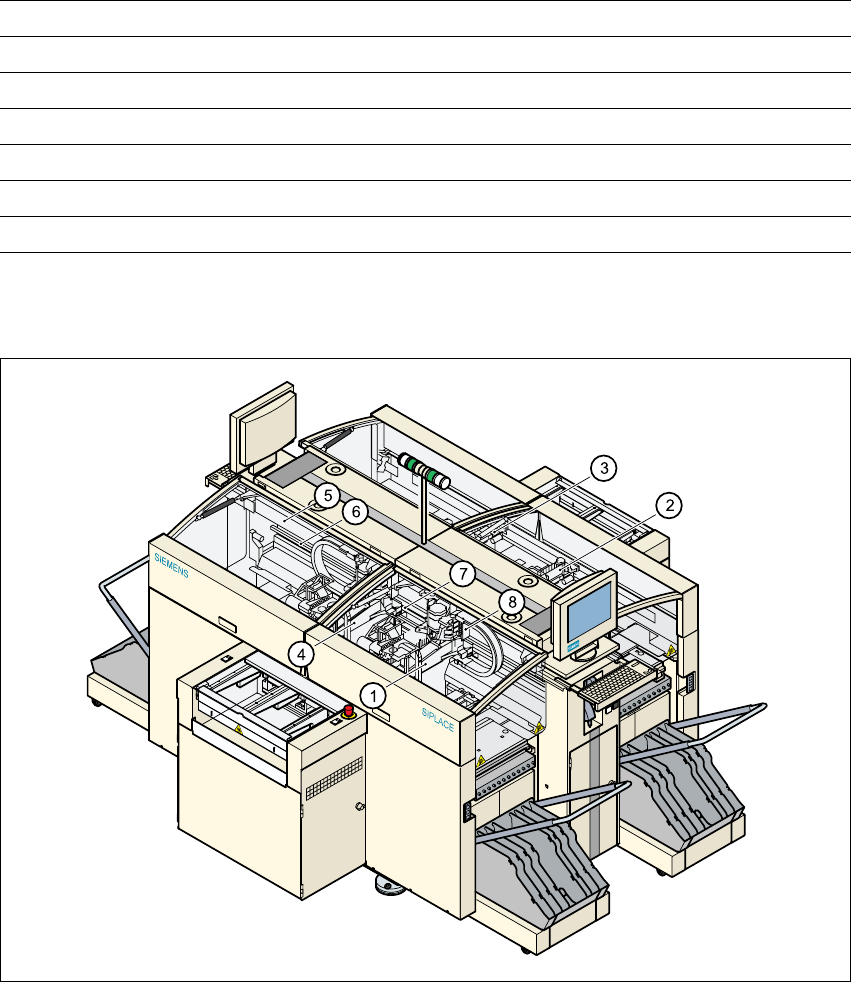
3.7.4 Structure of the Y axis
3
Fig. 3.7 - 3 Structure of the Y axis
Drive Three-phase AC servomotor/toothed belt
Maximum speed 2.5 m/sec.
Traversing path 375 mm
Distance measuring system Metal linear scale
Measuring length 400 mm
Scale length 420 mm
Resolution 1 µm
(1) Gantry 1 (5) Permanent magnet
(2) Gantry 2 (6) Guide system
(3) Gantry 3 (7) Measuring system
(4) Gantry 4 (8) Adapter plate