00193411-02.pdf - 第93页
User Manual SIPLAC E HS-60 3 Technical data Software version SR.503.xx 07/2003 US Edition 3.9 Overview of the modules - vision modules 93 3.9.1 Component vision module (st anda rd camera) on the 12-segment Collect&Pl…
3 Technical data User Manual SIPLACE HS-60
3.9 Overview of the modules - vision modules Software version SR.503.xx 07/2003 US Edition
92
3.9 Overview of the modules - vision modules
Each placement system has
– four component vision modules on the placement heads and
– four PCB vision modules on the underside of the X axis gantries.
The vision analysis units are located in the control unit for the placement system. The component
vision module is used to determine:
– the precise position of the components at the nozzle and
– the geometry of the package form.
The PCB vision module uses fiducials on the PCBs to determine:
– the position of the PCB,
– its rotation angle
– and the PCB skew.
The PCB vision module also uses fiducials on the feeder modules to determine the exact pick-up
position of components. This is particularly important for small components.
User Manual SIPLACE HS-60 3 Technical data
Software version SR.503.xx 07/2003 US Edition 3.9 Overview of the modules - vision modules
93
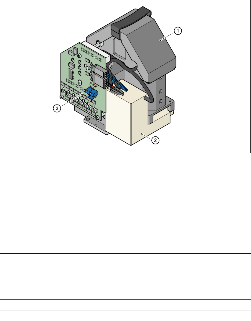
3.9.1 Component vision module (standard camera) on the 12-segment
Collect&Place head
3.9.1.1 Structure
3
Fig. 3.9 - 1 Component vision module (standard camera) on the 12-segment Collect&Place head
3
(1)Component camera, lens and illumination
(2)Camera amplifier
(3)Illumination control
3.9.1.2 Technical data
3
Component dimensions 0.5 mm x 1.0 mm to 18.7 mm x 18.7 mm
Range of components 0402 to PLCC44
including BGA, µBGA, flip-chip, TSOP, QFP
PLCC, SO to SO32, DRAM
Min. lead pitch 0.5 mm
Field of vision 24 mm x 24 mm
Method of illumination Front-lighting (3 levels, programable as required)
3 Technical data User Manual SIPLACE HS-60
3.9 Overview of the modules - vision modules Software version SR.503.xx 07/2003 US Edition
94
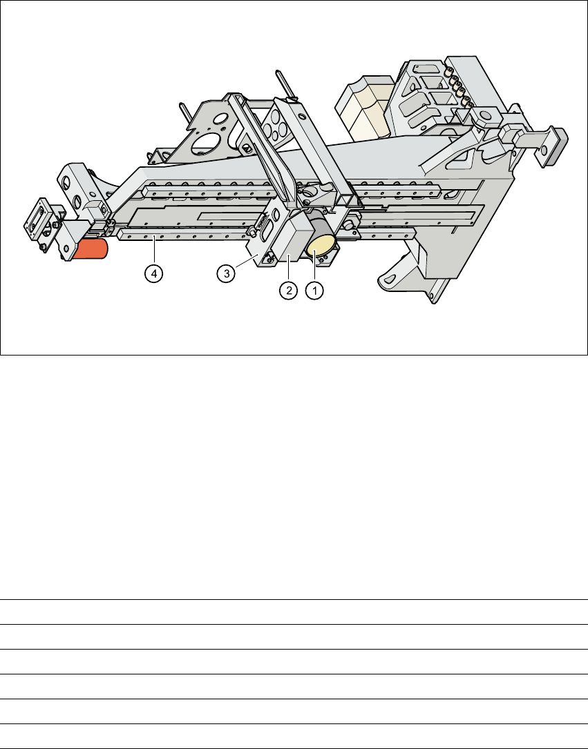
3.9.2 PCB vision module (standard camera)
3.9.2.1 Structure
3
Fig. 3.9 - 2 PCB vision camera (standard), gantry - view from below
3
(1) PCB camera, lens and illumination
(2) Camera amplifier
(3) Head mount
(4) Gantry
3.9.2.2 Technical data
Fiducials Up to 3 per placement program
Library size Up to 255 fiducial types - system fiducials ≥ 249
Image processing Geometric alignment
Method of illumination Front-lighting
Recognition time per fiducial/bad fiducial 0.4 s
Field of vision 5.7 mm x 5.7 mm