00193411-02.pdf - 第86页
3 Technical data User Manual SIPLACE HS-60 3.7 Overview of the modules - gantries Software version SR .503.xx 07/2003 US Edition 86 3.7 Overv iew of th e modules - gantries 3.7.1 Position of the gantries 3 Fig. 3.7 - 1 P…
User Manual SIPLACE HS-60 3 Technical data
Software version SR.503.xx 07/2003 US Edition 3.6 Overview of the modules - controls
85
3.6.3.1 Controls on the left / right-hand operator panel of the placement system
The two operator panel have identical control functions.
Monitor, keyboard, Start and Stop buttons 3
There is a monitor and a keyboard on both sides of the placement machine. They are arranged
so that any person who is at least 1.60 m tall can work comfortably and efficiently.
The Start and Stop buttons are located beneath the keyboard. The on-screen dialog will occasion-
ally prompt you to activate certain actions using buttons, and this arrangement will make it easier
for you both to activate and to interactively control these actions.
Key switch 3
The key switch is located on the left-hand operator panel beneath the Start and Stop buttons. It is
only needed for setting up and servicing work so, for reasons of efficiency, it is positioned near the
Start and Stop buttons.
Main switch 3
The main power switch is part of the power supply unit, so it is positioned on the left-hand side of
operator panel. It is located here because it is only needed for servicing and maintenance work
and is therefore not subject to frequent use.
Component barcode reader (option) 3
The four component trolleys for supplying components are arranged on the right and left of the
placement system. For this reason, the component barcode readers are also located in the central
console. It enables the operators to work comfortably and efficiently during the component set-up
and filling checks.
3.6.3.2 Controls on the input and output sides of the placement machine
The controls on the input and output sides of the placement machine perform identical functions.
EMERGENCY-STOP buttons and Start button 3
There is an emergency stop button and two Start buttons on both the input and output sides of the
PCB conveyor. This arrangement was adopted for the emergency stop buttons because it enables
them to be reached quickly and easily from any position.
In addition, it is important to have an unrestricted view of the placement heads and placement area
during preventive maintenance, servicing and setting up work in order to be able to check all the
operations carried out inside the machine. This particularly important during testing phases or
when starting single functions, for example.
3 Technical data User Manual SIPLACE HS-60
3.7 Overview of the modules - gantries Software version SR.503.xx 07/2003 US Edition
86
3.7 Overview of the modules - gantries
3.7.1 Position of the gantries
3
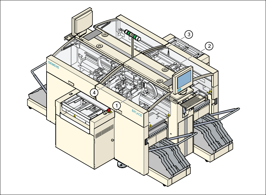
Fig. 3.7 - 1 Position of the gantries
3
(1) Gantry 1 (sector 1)
(2) Gantry 2 (sector 2)
(3) Gantry 3 (sector 3)
(4) Gantry 4 (sector 4)
The gantry system consists of two functional groups
– X axis and
–Y axis
User Manual SIPLACE HS-60 3 Technical data
Software version SR.503.xx 07/2003 US Edition 3.7 Overview of the modules - gantries
87
3.7.2 Structure of the X axis
3
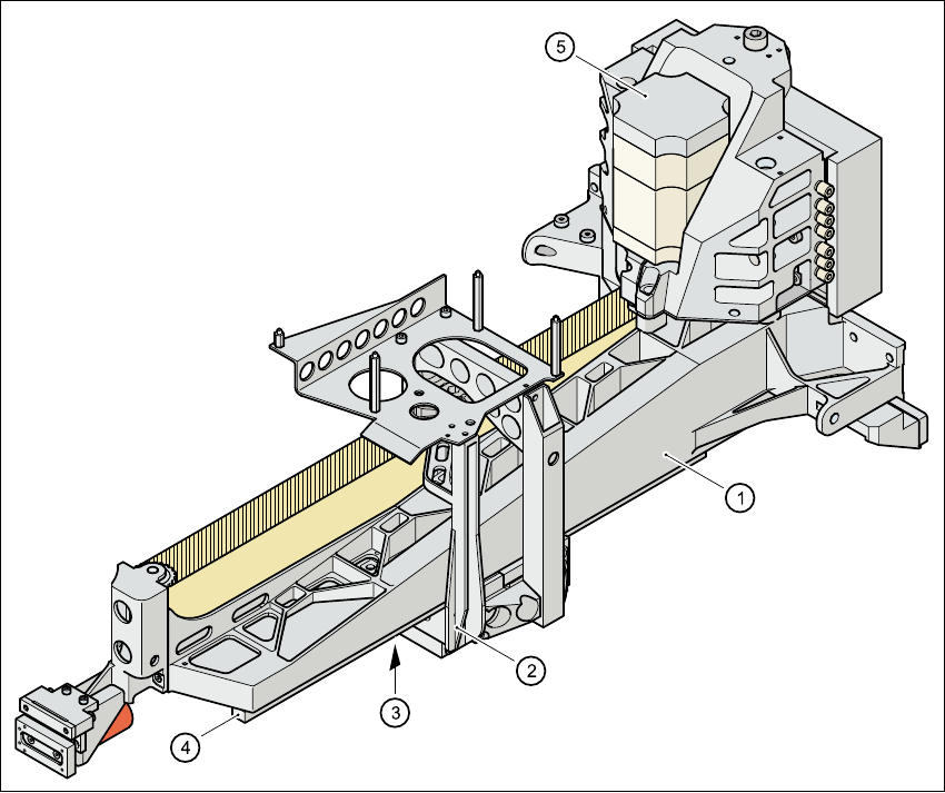
Fig. 3.7 - 2 Structure of the X axis
The X axis essentially consists of the following main modules:
– Gantry arm (1)
– Head mount (2)
– Linear measuring system (3)
– X axis guide system (4)
– X axis three-phase AC servomotor (5)
The head mount holds the following components
– Sub-gantry camera (camera for the PCB vision module)
– Head board
– Measuring head for the X axis measuring system
– Collect&Place head