00193411-02.pdf - 第44页
2 Operational safety User Manual SIPLACE HS-60 2.5 Safety equipment Software version SR. 503.xx 07/2003 US Edition 44 2.5 S afety equipment 2.5.1 Protectiv e covers 2 Fig. 2.5 - 1 Protec tive covers (1) P rotective cover…
User Manual SIPLACE HS-60 2 Operational safety
Software version SR.503.xx 07/2003 US Edition 2.4 Safety instructions for operating the machine
43
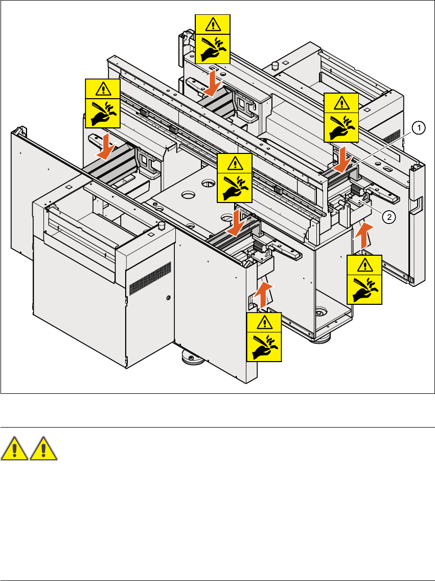
2.4.6 Safety instructions for the tape cutter
2
Fig. 2.4 - 3 Safety instructions for the tape cutter
WARNING RISK OF CUTTING! 2
Æ Never reach down into the used tape channel (Pos. 1) from above with bare hands, even if the
machine is switched off.
Æ Similarly, even when the machine is switched off, do not reach up from below with bare hands
into the ejection opening of the tape cutter (Pos. 2), e.g. to remove waste used tape.
Æ To remove waste used tape, it is essential to switch the machine off first and put on very sub-
stantial protective gloves, as the tape cutter bars are extremely sharp.
2 Operational safety User Manual SIPLACE HS-60
2.5 Safety equipment Software version SR.503.xx 07/2003 US Edition
44
2.5 Safety equipment
2.5.1 Protective covers
2
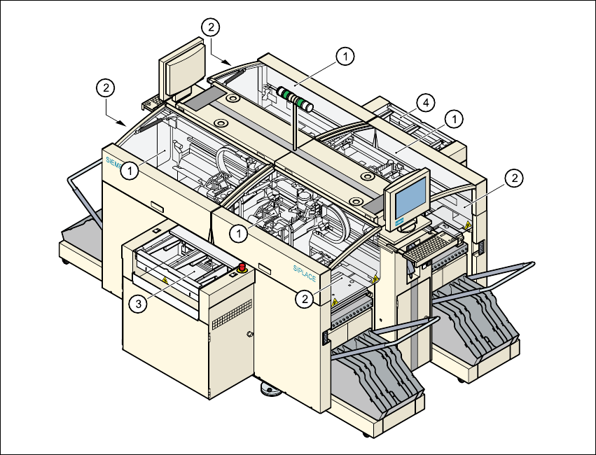
Fig. 2.5 - 1 Protective covers
(1) Protective covers
(2) Safety panels
(3) Cover and guard on the input belt
(4) Cover and guard on the output conveyor
The travelling range of the gantries has four protective covers that can be swung upwards. There
are side screens to prevent access to the inside of the machine from the side. Access to the PCB
conveyor is protected by covers, which can be pivoted upwards, over the input and output belts
and guards on both belts.
User Manual SIPLACE HS-60 2 Operational safety
Software version SR.503.xx 07/2003 US Edition 2.5 Safety equipment
45
Function 2
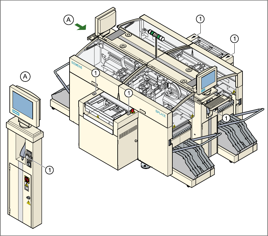
If one of the protective covers has been swung upwards or one of the covers on the PCB conveyor
has been lifted, the power supply to the gantry axes is cut off immediately. The gantry axes stop
moving. The message "Close cover" is displayed on the screen.
Æ Close the protective covers and press one of the Start buttons to continue placement.
2
Fig. 2.5 - 2 Position of the start button (white) on the machine
2
(1) Start button (white) on the machine