00193411-02.pdf - 第175页
User Manual SIPLAC E HS-60 7 Station extensions Software version SR.503.xx 07/2003 US Edition 7.7 DCA camera on the 12-segment Collect&Place head 175 7.7 DCA cam era on th e 12-segme nt C ollect& Place head 7 Fig…
7 Station extensions User Manual SIPLACE HS-60
7.6 Fine calibration Software version SR.503.xx 07/2003 US Edition
174
7
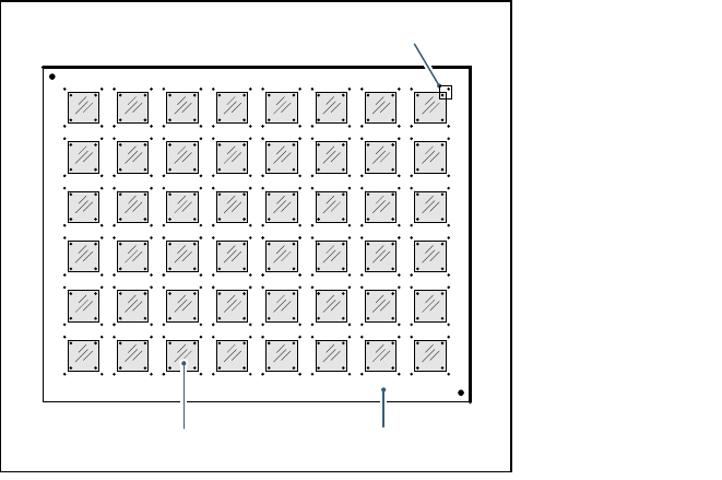
Fig. 7.6 - 1 Fine calibration principle
Immediately after placement, the PCB camera takes four sets of images of the associated refer-
ence fiducials on both PCB and component. The analysis program is then used to determine the
placement offset in the X/Y direction and the angular deviation. The offset values are used to cal-
culate the corrected values, which are then entered in the machine data (FK_off.ma).
7.6.5 Measuring modes
The following measurement modes can be selected:
– Measure the values for an individual placement head.
– Measure the values for all the placement heads in a placement area.
– Measure the values for the entire machine.
The measurement can be repeated as often as required, with or without replacing the CERAM
components.
7.6.6 Displaying and analyzing measured values
The measured values can be displayed graphically on screen and saved to diskette. The following
display options are available:
– Display measured values for each individual placement head.
– Display the measured values for each segment.
– Display measured values for the X or Y direction or angular measurement.
Glass components Glass PCB
Field of view of the PCB camera
User Manual SIPLACE HS-60 7 Station extensions
Software version SR.503.xx 07/2003 US Edition 7.7 DCA camera on the 12-segment Collect&Place head
175
7.7 DCA camera on the 12-segment Collect&Place
head
7
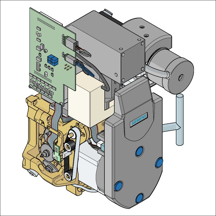
Fig. 7.7 - 1 DCA camera on the 12-segment Collect&Place head
7
(1) DCA camera
(2) 12-segment Collect&Place head

7 Station extensions User Manual SIPLACE HS-60
7.7 DCA camera on the 12-segment Collect&Place head Software version SR.503.xx 07/2003 US Edition
176
7.7.1 Description
With the DCA camera, the 12-segment Collect&Place head is able to optically center and place
components of the order of magnitude of 0.6 mm x 0.3 mm to 13mm x 13mm. The DCA package
optimizes the speed and accuracy when placing high-speed flip chips and bare die components.
7.7.2 Technical data
Component range 0201 to 13 mm x 13 mm
Component specification
Max. height
Min. lead pitch
Min. bump pitch
Min. ball/bump diameter
Min. dimensions
Max. dimensions
Max. weight
6 mm
0.4 mm
0.2 mm
0.11 mm
0.6 mm x 0.3 mm
13 mm x 13 mm
2 g
Z axis stroke Max. 16 mm
Programmable set-down force 2.4 to 5.0 N
Nozzle types 9 xx
Max. placement rate 15,000 comp/h
Angular accuracy ± 0.7° / 4 sigma
Placement accuracy of the DCA camera ± 75 µm / 4 sigma (gantry 4)
± 80 µm / 4 sigma (gantries 1-3)