00193411-02.pdf - 第174页
7 Station extensions User Manual SIPLACE HS-60 7.6 Fine calibration Software version S R.503.xx 07/2003 US Edition 174 7 Fig. 7.6 - 1 Fine ca libration principle Immediatel y after placem ent, the PCB came ra takes four …

User Manual SIPLACE HS-60 7 Station extensions
Software version SR.503.xx 07/2003 US Edition 7.6 Fine calibration
173
7.6 Fine calibration
7.6.1 Overview
Fine calibration involves measuring the machine’s placement offset and determining the required
correction from this value. The ‘Fine calibration’ measuring program is integrated into the SIT-
EST program, and a detailed description of the measuring procedure is given in the ‘Fine calibra-
tion’ instructions (part no. 00191655-01).
CAUTION
The SITEST program is password-protected. It must only be called up and used by SiemensDe-
matic engineers or appropriately trained personnel. 7
7.6.2 System requirements
The following system requirements must be fulfilled in order to use the fine calibration program:
Machine type HS-60
Station computer software version 503.xx or later
SITEST version 503.xx or later
7.6.3 Measuring equipment and tools
The following are supplied as standard:
– Mapping plate (glass plate in a metal frame)
– Double-sided transparent adhesive film
– Lighting unit
– CERAM components in the feeder for the 12-segment Collect&Place head
7.6.4 Description of the functions
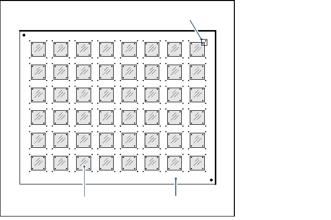
A large number of CERAM components are placed on a glass PCB covered with adhesive film.
On the top of the CERAM components there are reference fiducials in each corner. The glass
PCB also has reference fiducials in the immediate vicinity of these component fiducials.
7 Station extensions User Manual SIPLACE HS-60
7.6 Fine calibration Software version SR.503.xx 07/2003 US Edition
174
7
Fig. 7.6 - 1 Fine calibration principle
Immediately after placement, the PCB camera takes four sets of images of the associated refer-
ence fiducials on both PCB and component. The analysis program is then used to determine the
placement offset in the X/Y direction and the angular deviation. The offset values are used to cal-
culate the corrected values, which are then entered in the machine data (FK_off.ma).
7.6.5 Measuring modes
The following measurement modes can be selected:
– Measure the values for an individual placement head.
– Measure the values for all the placement heads in a placement area.
– Measure the values for the entire machine.
The measurement can be repeated as often as required, with or without replacing the CERAM
components.
7.6.6 Displaying and analyzing measured values
The measured values can be displayed graphically on screen and saved to diskette. The following
display options are available:
– Display measured values for each individual placement head.
– Display the measured values for each segment.
– Display measured values for the X or Y direction or angular measurement.
Glass components Glass PCB
Field of view of the PCB camera
User Manual SIPLACE HS-60 7 Station extensions
Software version SR.503.xx 07/2003 US Edition 7.7 DCA camera on the 12-segment Collect&Place head
175
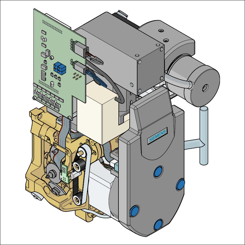
7.7 DCA camera on the 12-segment Collect&Place
head
7
Fig. 7.7 - 1 DCA camera on the 12-segment Collect&Place head
7
(1) DCA camera
(2) 12-segment Collect&Place head