00193411-02.pdf - 第156页
7 Station extensions User Manual SIPLACE HS-60 7.2 Component barc ode reader Software v ersion SR.503.xx 07/2003 US Edition 156 7.2 Com ponent b arcode re ader 7.2.1 Gener al With the p lacement system, a barcod e reader…
User Manual SIPLACE HS-60 7 Station extensions
Software version SR.503.xx 07/2003 US Edition 7.1 Nozzle changer for the 12-segment Collect&Place head
155
PLEASE NOTE
Make sure that you insert the magazine so that the centering pins slide into the centering hole
(item 3) and slot (item 4). 7
Æ First place the side of the magazine with the numbered nozzles 1, 2, 3 and 4 on the base. The
retaining clamp (item 2) must slide into the slot in the magazine.
Æ Push the spring hook away from the magazine.
Æ Press the magazine so that it lies flat on the base, then release the spring hook. The spring
hook must latch into place.
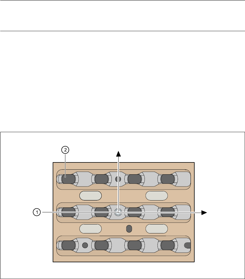
7.1.6 Position detection
There is a position detection fiducial on every magazine.
7
Fig. 7.1 - 4 Nozzle changer - position detection
7
(1) Positioning fiducial
(2) Position of the nozzles in the magazine with respect to the positioning fiducial
12 3
4
10 11
12
Y
X
9
5
6
7
8
7 Station extensions User Manual SIPLACE HS-60
7.2 Component barcode reader Software version SR.503.xx 07/2003 US Edition
156
7.2 Component barcode reader
7.2.1 General
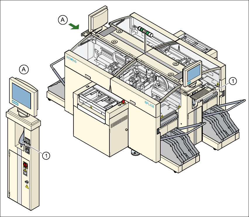
With the placement system, a barcode reader can be used to check that the track allocation is
correct and to read component data from component reels. A barcode reader is attached to both
of the operator panels on the placement system.
7
Fig. 7.2 - 1 Component barcode reader
(1) Barcode reader

User Manual SIPLACE HS-60 7 Station extensions
Software version SR.503.xx 07/2003 US Edition 7.2 Component barcode reader
157
Track allocation 7
Four-digit barcode strips are attached to the lateral safety screens for the purposes of track allo-
cation. The first digit is used to identify the component table (1, 2, 3, or 4), while the remaining
three digits specify the track number. There are also return barcodes at both ends of the barcode
strip. The barcode strips are numbered consecutively in intervals of two (1, 3, 5, 7...) and each
represents 2 tracks (barcode 1 = track 1 and 2).
Components 7
Data can be read from the component reels to compare the stock of components against the quan-
tity specified in the set-up file (refill check), for example.
An audible signal is given when each dataset has been read successfully.
PLEASE NOTE 7
The component barcode reader option must be configured on the line computer or the SIPLACE
Pro.
Barcodes that start with the number 1, 2, 3, or 4 and are five digits long are interpreted as track
barcodes. All other barcodes that do not start with number 1, 2, 3, or 4 are regarded as compo-
nent barcodes.
7.2.2 Technical data
7
Connection Station computer
Data entry Barcode reader or keyboard
Number of characters Max. 40 / single conveyor
Max. 2 x 20 / dual conveyor
Not permissible Barcodes starting with a 1, 2, 3, or 4 and less than
5 characters long
Number of barcodes Up to 6 per component
Filter for suppressing data Up to 1 per barcode
Preset barcode types Code 39 (standard or ASCII)
Code 2 of 5, interleaved and normal,
Code 128, UPC/EAN/JAN codes
(others available upon request)
Max. resolution 0.13 mm
Scanning speed 36 scans/sec.
Laser class IEC class 1 - VDE0837
Degree of protection IP 64