00193411-02.pdf - 第178页
7 Station extensions User Manual SIPLACE HS-60 7.9 Component s ensor Software version SR.503.xx 07/2003 US Edition 178 7.9 Com ponent se nsor 7.9.1 Function The com ponent sen sor is fix ed to the u ndersi de of the c as…
User Manual SIPLACE HS-60 7 Station extensions
Software version SR.503.xx 07/2003 US Edition 7.8 DCA camera
177
7.8 DCA camera
7.8.1 Structure
7
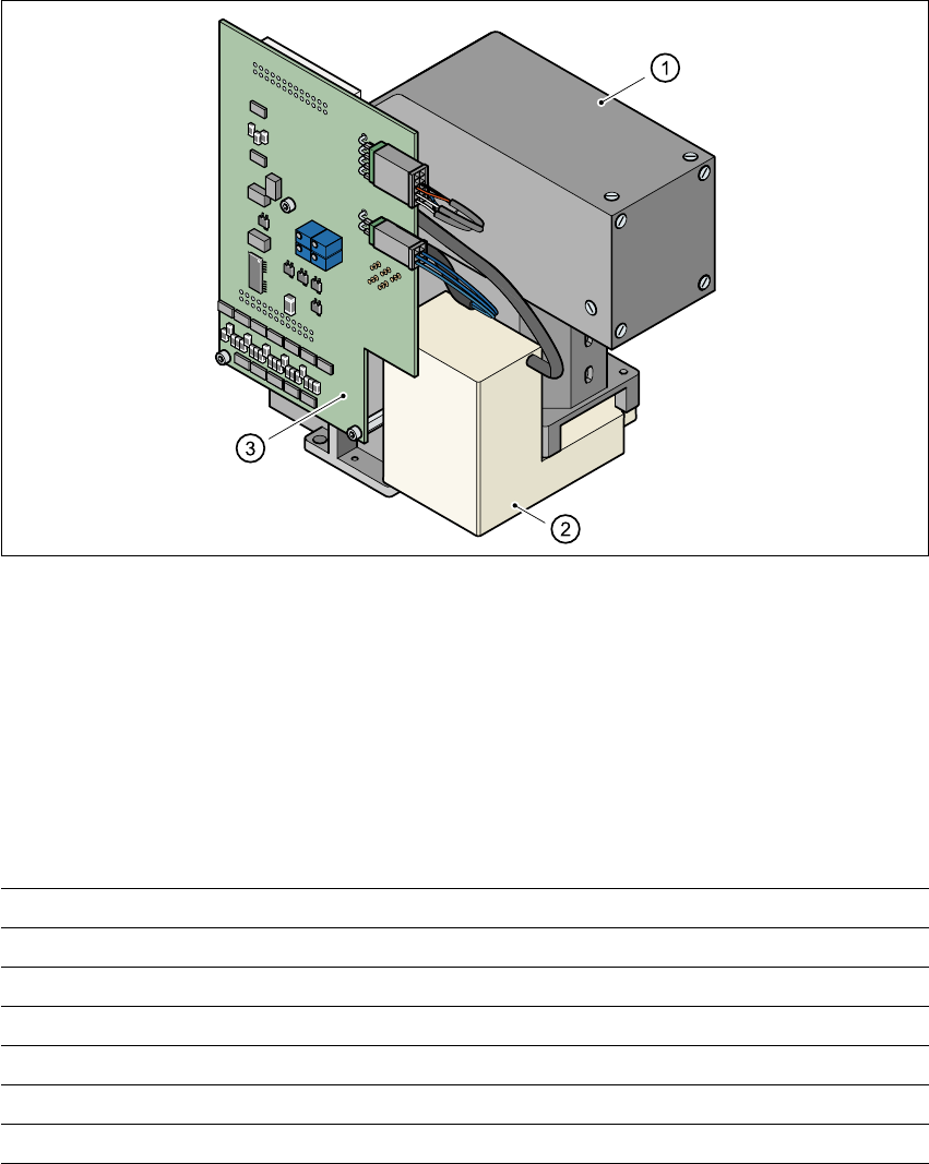
Fig. 7.8 - 1 DCA camera
7
(1) PCB camera, lens and illumination
(2) Camera amplifier
(3) Illumination control
7
7.8.2 Technical data
7
7
Component dimensions 0.6 mm x 0.3 mm to 13 mm x 13 mm
Component range 0201 up to 13 mm x 13 mm, flip-chip, bare die
Min. lead pitch 0.4 mm
Minimum bump pitch 0.2 mm
Min. ball/bump diameter 0.11 mm
Field of view 15.7 mm x 15.7 mm
Illumination method Front lighting (four levels programmable as required)
7 Station extensions User Manual SIPLACE HS-60
7.9 Component sensor Software version SR.503.xx 07/2003 US Edition
178
7.9 Component sensor
7.9.1 Function
The component sensor is fixed to the underside of the casing of the 12-segment Collect&Place
head (see Fig. 7.9 - 2
). It measures the height of the nozzle and the height of the nozzle with the
component. The component height is then determined from the two values. The sensor thus also
checks that the component is actually present.
Component heights from 0.1 to 4 mm can be checked. It is also possible to determine whether
the component is in its normal position or is sticking to the nozzle on edge. This requires the dif-
ference between the height and width of the component to be at least 100 µm, i.e. component
sizes 0603 or larger.
7
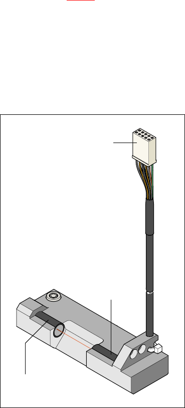
Fig. 7.9 - 1 Component sensor
To the ‘head gantry
distributor’ board
Infrared LED
Phototransistor
(receiver)
User Manual SIPLACE HS-60 7 Station extensions
Software version SR.503.xx 07/2003 US Edition 7.9 Component sensor
179
7
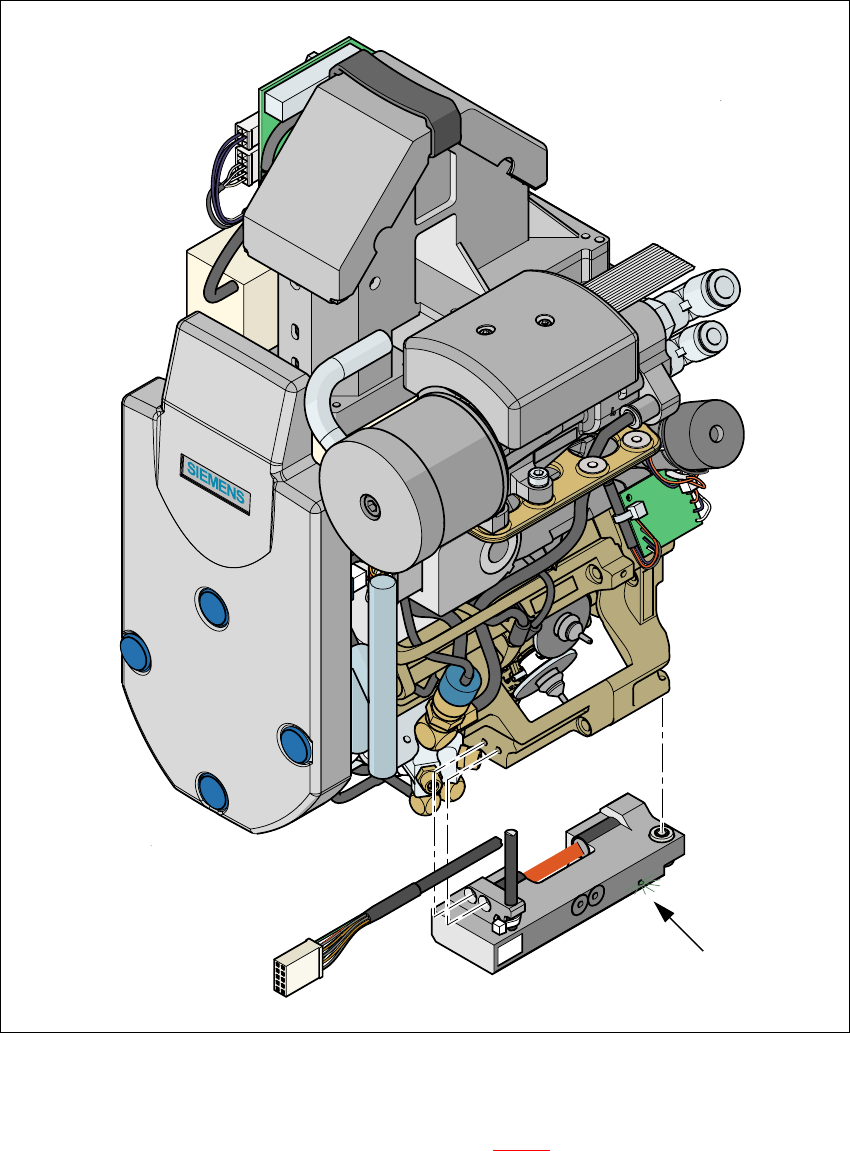
Fig. 7.9 - 2 Placement head with component sensor
7
The green control LED lights up if the component sensor is switched on and the invisible IR light
beam for the component height measurement (see Fig. 7.9 - 2
red strip) is not interrupted. You
can interrupt the IR beam to check that it is working correctly. The green LED must go out.
Green control LED