00193411-02.pdf - 第39页
User Manual SIPLAC E HS-60 2 Operational safety Software version SR.503.xx 07/2003 US Edition 2.4 Safety instructions for operating the machine 39 2.4 Safety instructions fo r operating the machine 2.4.1 Safety inst ruct…

2 Operational safety User Manual SIPLACE HS-60
2.3 Laser classification Software version SR.503.xx 07/2003 US Edition
38
2.3.3 Laser class 2
The following modules are assigned to laser class 2:
– Laser light barrier, placement area 1 in the PCB conveyor
– Laser light barrier, placement area 2 in the PCB conveyor
– PCB barcode scanner
2
2
Laser radiation
Do not look into beam!
User Manual SIPLACE HS-60 2 Operational safety
Software version SR.503.xx 07/2003 US Edition 2.4 Safety instructions for operating the machine
39
2.4 Safety instructions for operating the machine
2.4.1 Safety instructions for closing the protective covers
To prevent any risk of injury when the protective covers on automatic placement machines are
closed, the owner must instruct his operators to use the protective covers exactly as specified in
the following instructions.
CAUTION RISK OF CRUSHING HANDS 2
IF THE PROTECTIVE COVERS ARE NOT CLOSED CORRECTLY
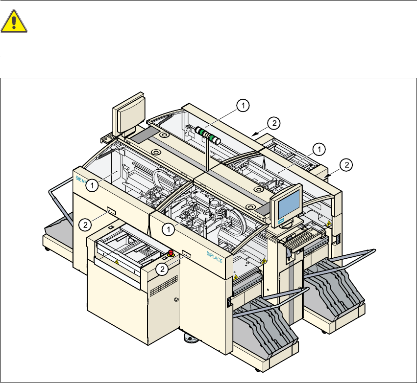
Fig. 2.4 - 1 Safety instructions for closing the protective covers
(1) Protective covers
(2) Recessed grips
2
Æ When opening or closing the protective covers, always hold the covers by the recessed grips.
2 Operational safety User Manual SIPLACE HS-60
2.4 Safety instructions for operating the machine Software version SR.503.xx 07/2003 US Edition
40
2.4.2 Safety instructions for docking the component trolley in or out
. 2
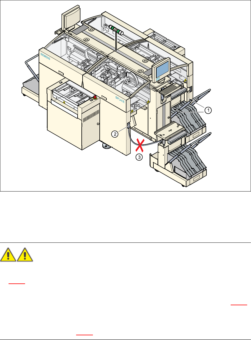
Fig. 2.4 - 2 Safety instructions on the component trolley
(1) Vertical gap between the placement system frame and the component trolley
(2) Plug for connecting the component trolley cable
(3) Connecting cable for compressed air and main power supply to the component trolley
WARNING 2
Æ Never reach into the gap between the component trolley and the machine base (item 1 in Fig.
2.4 - 2
).
Æ The power cable for the component trolley must not be connected to the machine socket, or
pulled out of it, unless the component trolley is docked on the machine (item 2 in Fig. 2.4 - 2
).
Æ Never connect the connecting cable for the component trolley to the socket on the placement
system and then operate the component trolley outside the machine via the compressed air
control unit (item 3 in Fig. 2.4 - 2).