00193411-02.pdf - 第58页
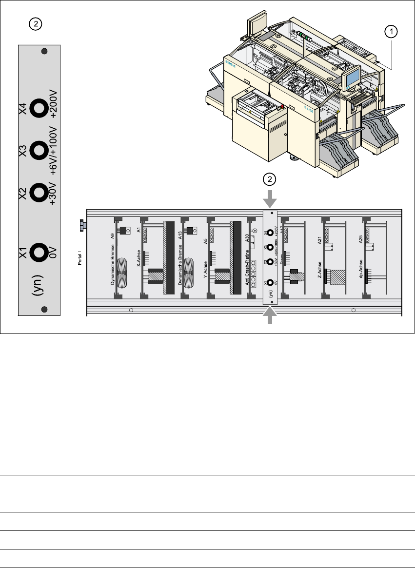
2 Operational safety User Manual SIPLACE HS-60 2.6 Residual voltages and discharge time s in the machine Software version SR. 503.xx 07/2003 US Edition 58 2 Fig. 2.6 - 1 T est sockets on t he voltmeter unit in the servo …

User Manual SIPLACE HS-60 2 Operational safety
Software version SR.503.xx 07/2003 US Edition 2.6 Residual voltages and discharge times in the machine
57
2.6 Residual voltages and discharge times in the
machine
If the EMERGENCY-STOP-button is pressed or the placement system is switched off, the 200 V
link voltage for the gantry axes and the 100 V link voltage for the star axes are discharged to harm-
less residual voltages in a very short time.
The voltages can be tapped off at test sockets X1 - X4 on the voltage measuring unit in the servo
unit.
WARNING 2
The placement system is supplied with 3 x 204 VAC (US version), 3 x 230 VAC, 3 x 380 VAC,
3 x 400 VAC or 3 x 415 VAC ± 5 %, 50/60 Hz main power voltage. This means that some parts of
the system carry potentially lethal voltages - even when switched off at the main power switch.
Incorrect handling of the placement system can therefore result in death or severe injury or con-
siderable damage to equipment.
Æ Always follow the applicable accident prevention and DIN regulations (particularly DIN EN 60
204, part 1).
Æ The guard over the servo unit must ONLY be opened by appropriately qualified and trained
personnel.
2 Operational safety User Manual SIPLACE HS-60
2.6 Residual voltages and discharge times in the machine Software version SR.503.xx 07/2003 US Edition
58
2
Fig. 2.6 - 1 Test sockets on the voltmeter unit in the servo unit
2
(1) Position of the servo unit
(2) Voltage measuring unit on the servo unit
2.6.1 Operating voltages, residual voltages and discharge times after pressing
the EMERGENCY-STOP button
2
Test sockets X2, X3, X4
measured to X1 (GND)
Voltage in normal
mode
Residual voltage
after emerg. stop
Discharge times
X2 + 30 VDC + 30 VDC -
X3 + 100 VDC < 10 VDC 50 sec
X4 + 200 VDC < 10 VDC 7 sec
User Manual SIPLACE HS-60 2 Operational safety
Software version SR.503.xx 07/2003 US Edition 2.7 Disabling the compressed air supply and discharging the pressure
59
2.6.2 Residual voltages and discharge times after switching off at the main switch
2
CAUTION
To avoid losing data, evaluate the following criteria before switching off your automatic placement
system (apart from in emergencies): 2
– Has the placement system finished transmitting machine, setup and panel data?
– Has the placement system finished processing the PCB?
– Has the placement system completed the run-up phase?
2.7 Disabling the compressed air supply and discharg-
ing the pressure
The compressed air working pressure is set to 0.54 MPa (5.4 bar). The position of the compressed
air unit is indicated by item 4 in Fig. 2.7 - 1
. The compressed air supply to the machine can be
interrupted using the shutoff valve (item 1 in Fig. 2.7 - 1
).
Æ Open the protective door.
Æ Turn the lever on the shutoff valve (item 1 in Fig. 2.7 - 1) from the vertical to the horizontal po-
sition.
Æ Watch the working pressure gauge and the pressure gauge for the compressed air supply to
the stopper (items 2 and 3 in Fig. 2.7 - 1
). When the automatic placement system is switched
on, the pressure discharges to 0 MPa (0 bar) within 1 minute.
CAUTION
When the machine is switched on, do not use the stop valve to interrupt the compressed air sup-
ply for more than 30 minutes. If you need to shut off the pneumatic system for longer in order to
carry out preventive maintenance or servicing work, you must switch the placement system off at
the main switch and disconnect it from the power supply.
Test sockets X2, X3, X4
measured to X1 (GND)
Residual voltages when
main power switch is off
Discharge times
X2 < 10 VDC < 2 sec
X3 < 10 VDC < 50 sec
X4 < 10 VDC < 7 sec