00193411-02.pdf - 第56页
2 Operational safety User Manual SIPLACE HS-60 2.5 Safety equipment Software version SR. 503.xx 07/2003 US Edition 56 2.5.5 Guard on the component t able locations DANGER 2 All loc ations mu st be equi pped with feeders …
User Manual SIPLACE HS-60 2 Operational safety
Software version SR.503.xx 07/2003 US Edition 2.5 Safety equipment
55
2
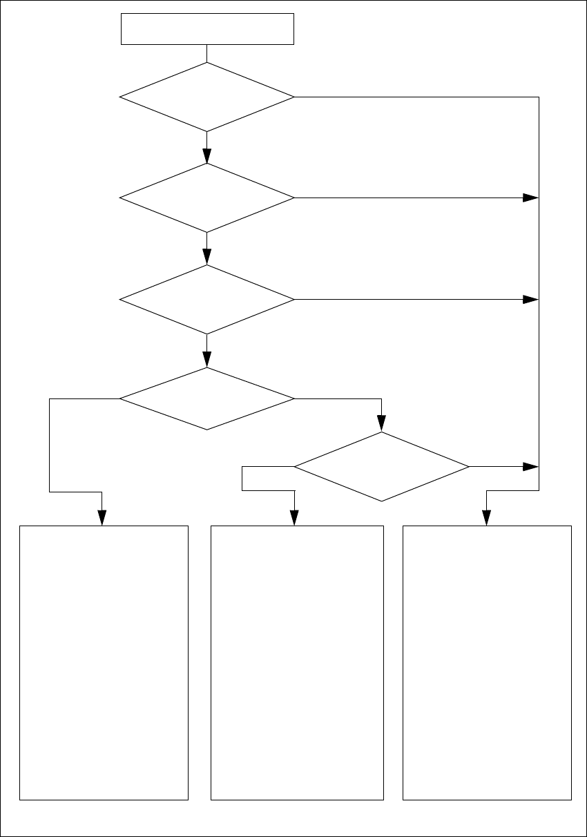
Fig. 2.5 - 7 Safety circuits
2
Compressed air
min. 0.65 MPa (6.5 bar)?
No
2
Start button pressed
2
EMERGENCY STOP
button pressed?
2
Protective cover open ?
2
Key switch
closed (position I)?
No
2
Component table
safety circuit interrupted?
Yes
No
No
Yes
Yes
No
2
Active
PCC*) Yes
Voltage
Y axis 200 V
X axis 200 V
Star axis 100 V
DP axis 30 V
Z axis 30 V
Active
PCB conveyor Yes
Lifting table Yes
PCB clamping Yes
Width adjustment Yes
Laser light barrier Yes
Used tape cutter Yes
Yes
2
Active
PCC*) No
Voltage
Y axis 0 V
X axis 0 V
Star axis 10 V
DP axis 30 V
Z axis 30 V
Active
PCB conveyor Yes
Lifting table No
PCB clamping No
Width adjustment Yes
Laser light barrier No
Used tape cutter No
2
Active
PCC*) No
Voltage
Y axis 0 V
X axis 0 V
Star axis 10 V
DP axis 30 V
Z axis 30 V
Active
PCB conveyor No
Lifting table No
PCB clamping No
Width adjustment No
Laser light barrier No
Used tape cutter No
2
*) PCC protective contactor combination
Yes
2 Operational safety User Manual SIPLACE HS-60
2.5 Safety equipment Software version SR.503.xx 07/2003 US Edition
56
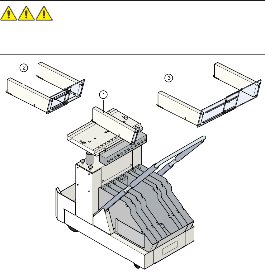
2.5.5 Guard on the component table locations
DANGER 2
All locations must be equipped with feeders in order to guarantee operational reliability. If there
are not enough feeders available, a guard ("dummy feeder") must be fitted in place of the feeder.
2
Fig. 2.5 - 8 Guard on the CO trolley
2
(1) Guard for 1 location part no. 00116961-01
(2) Guard for 6 to 10 locations part no. 00116962-01
(3) Guard for 11 to 20 locations part no. 00116963-01

User Manual SIPLACE HS-60 2 Operational safety
Software version SR.503.xx 07/2003 US Edition 2.6 Residual voltages and discharge times in the machine
57
2.6 Residual voltages and discharge times in the
machine
If the EMERGENCY-STOP-button is pressed or the placement system is switched off, the 200 V
link voltage for the gantry axes and the 100 V link voltage for the star axes are discharged to harm-
less residual voltages in a very short time.
The voltages can be tapped off at test sockets X1 - X4 on the voltage measuring unit in the servo
unit.
WARNING 2
The placement system is supplied with 3 x 204 VAC (US version), 3 x 230 VAC, 3 x 380 VAC,
3 x 400 VAC or 3 x 415 VAC ± 5 %, 50/60 Hz main power voltage. This means that some parts of
the system carry potentially lethal voltages - even when switched off at the main power switch.
Incorrect handling of the placement system can therefore result in death or severe injury or con-
siderable damage to equipment.
Æ Always follow the applicable accident prevention and DIN regulations (particularly DIN EN 60
204, part 1).
Æ The guard over the servo unit must ONLY be opened by appropriately qualified and trained
personnel.