00193411-02.pdf - 第45页
User Manual SIPLAC E HS-60 2 Operational safety Software version SR.503.xx 07/2003 US Edition 2. 5 Safety equipment 45 Function 2 If one of the prote ctive c overs ha s been s wung u pwards or one o f the cover s on th e…
2 Operational safety User Manual SIPLACE HS-60
2.5 Safety equipment Software version SR.503.xx 07/2003 US Edition
44
2.5 Safety equipment
2.5.1 Protective covers
2
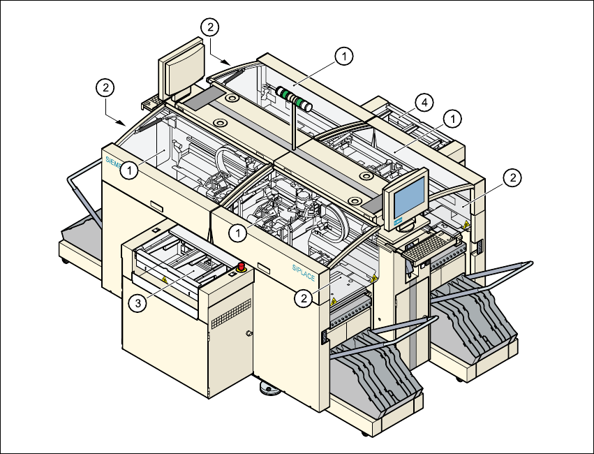
Fig. 2.5 - 1 Protective covers
(1) Protective covers
(2) Safety panels
(3) Cover and guard on the input belt
(4) Cover and guard on the output conveyor
The travelling range of the gantries has four protective covers that can be swung upwards. There
are side screens to prevent access to the inside of the machine from the side. Access to the PCB
conveyor is protected by covers, which can be pivoted upwards, over the input and output belts
and guards on both belts.
User Manual SIPLACE HS-60 2 Operational safety
Software version SR.503.xx 07/2003 US Edition 2.5 Safety equipment
45
Function 2
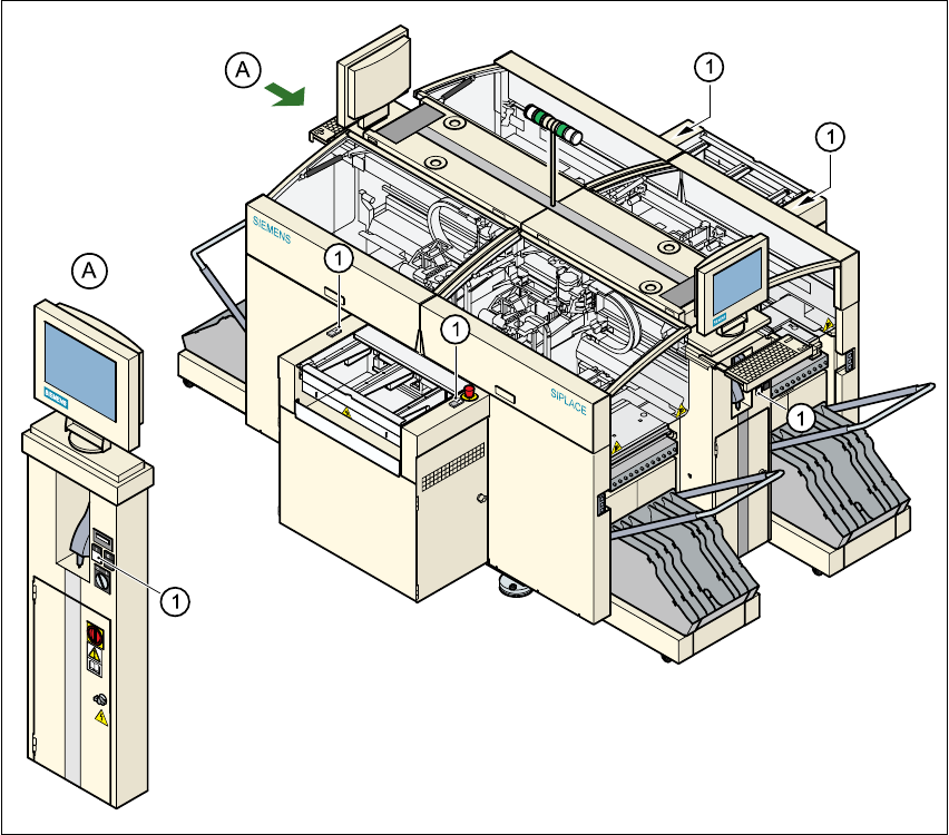
If one of the protective covers has been swung upwards or one of the covers on the PCB conveyor
has been lifted, the power supply to the gantry axes is cut off immediately. The gantry axes stop
moving. The message "Close cover" is displayed on the screen.
Æ Close the protective covers and press one of the Start buttons to continue placement.
2
Fig. 2.5 - 2 Position of the start button (white) on the machine
2
(1) Start button (white) on the machine
2 Operational safety User Manual SIPLACE HS-60
2.5 Safety equipment Software version SR.503.xx 07/2003 US Edition
46
2.5.2 Guard on the input/output belt
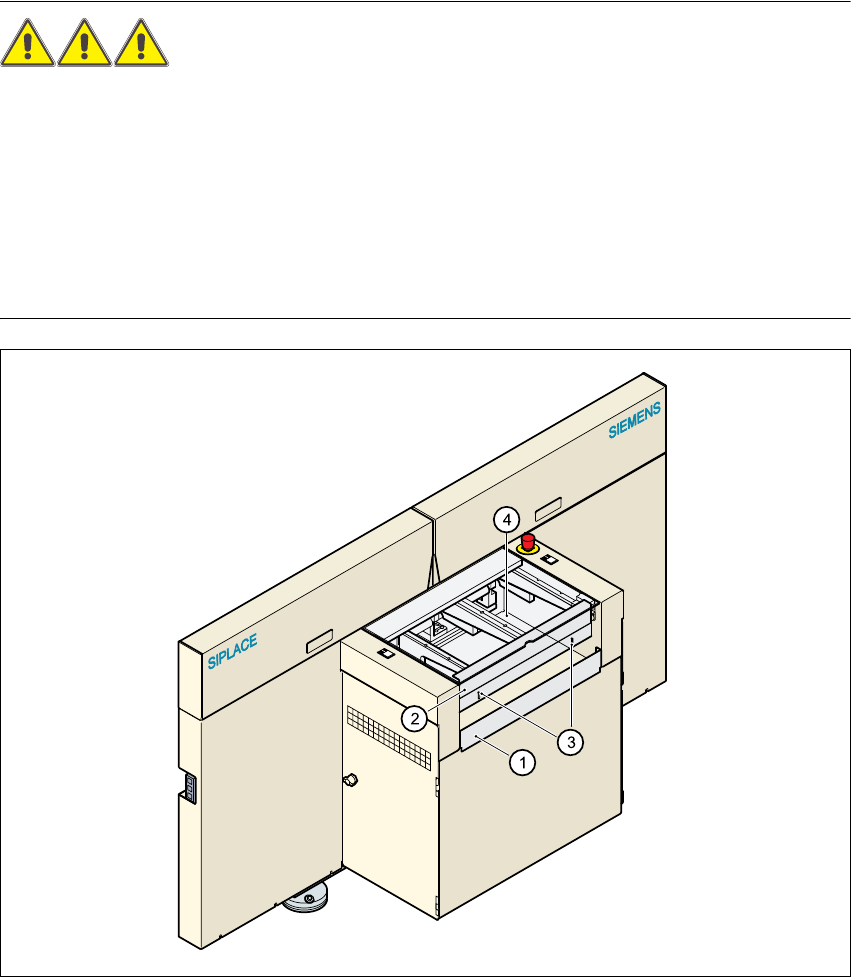
DANGER OF CRUSHING! 2
The guard must always be set to the height of the circuit board to be processed. The gap between
the guard and the safety bar should be kept as small as possible. The guard is mounted on the
input and output belts of the PCB conveyor.
Æ Never reach through the gap into the inside of the machine. There is a danger of crushing from
the lifting table.
Æ Adjust the height of the guard at the slots so that the circuit board to be processed can be car-
ried through.
2
Fig. 2.5 - 3 Guard at the input and output belts of the machine
2
(1) Safety bar (fixed)
(2) Guard (adjustable)
(3) Slots for adjusting the height
(4) Cover