X-Series-Maintenance-Manual(1).pdf - 第113页
Major Maintenance Performing Maintenance Tasks Maintenance Tasks for C&P6/12 Head Maintenance Manual SIPLACE X Series 113 Vacuum Gene rator 5.7.3.8 Vacuum Generator ► Press the friction wheel of the turning station a…
Major Maintenance
Maintenance Tasks for C&P6/12 Head Performing Maintenance Tasks
112 Maintenance Manual SIPLACE X Series
Valve adjustment drives
5.7.3.6 Valve adjustment drives
Turning station
5.7.3.7 Turning station
NOTICE
Remove front part of head
You will need to dismantle the front section of the head for this maintenance work.
NOTICE
DLM4 at the DX series
The DLM4 head offers only one valve drive in the placement and pick-up position.
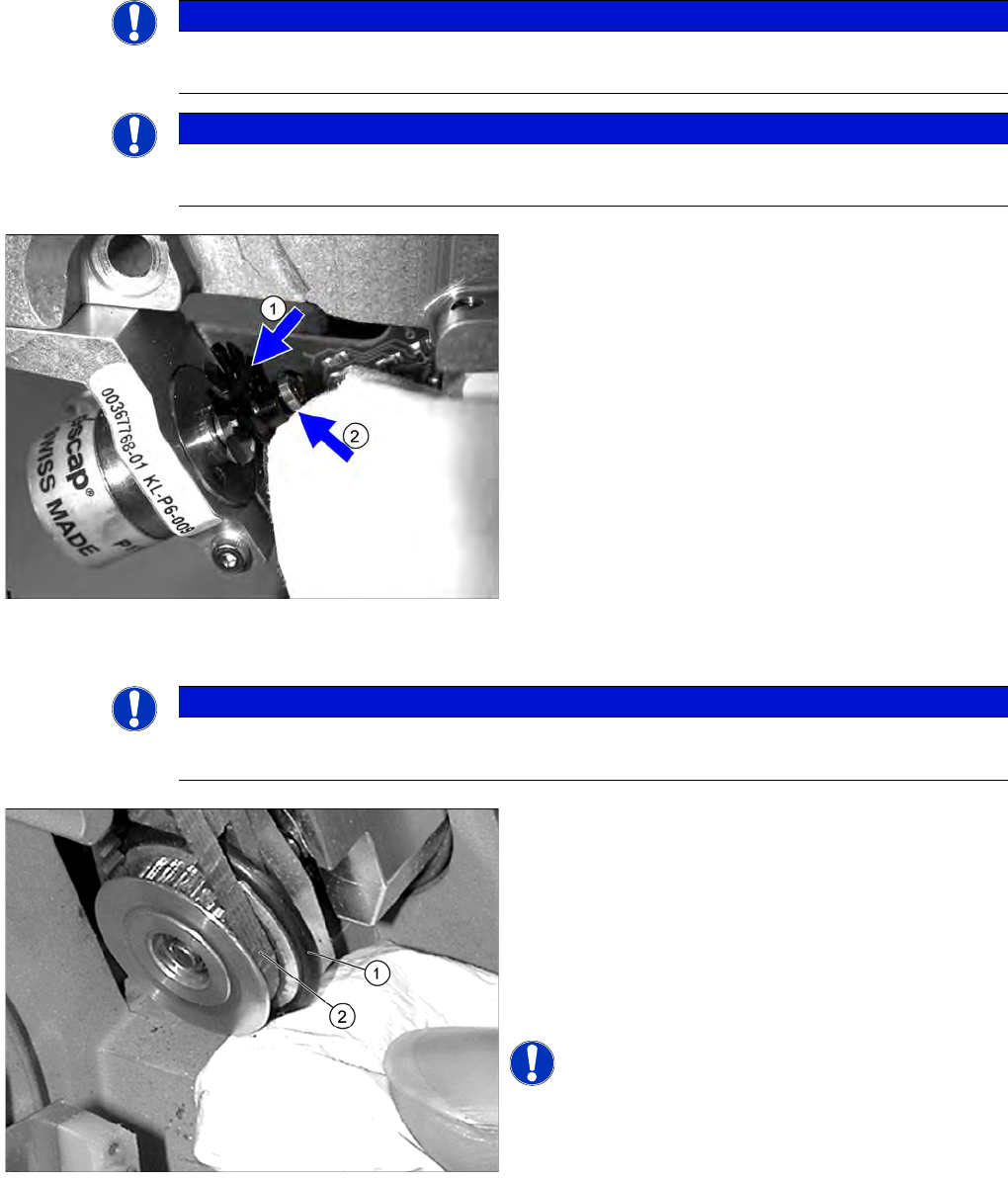
► Clean the valve adjusting drive and wipe the space
between the disk (1) and the motor mount dry with a
lint-free cloth.
► Wipe the ball bearings (2) dry with a lint-free cloth.
► Check that the ball bearing is working correctly. If you
have any problems, replace the valve adjustment
drive. For removal and installation details, read the
service manual for the respective machine.
► Remove any visible dirt.
► Repeat these steps for all valve adjustment drives.
NOTICE
Item-No. turning station
The turning stations at DLM3 and at DLM4 are different.
► Wipe the black O-ring (1) for the turning station clean
with a lint-free cloth moistened with ethanol.
► Check the O-ring for damage and replace if
necessary. For removal and installation details, read
the service manual for the respective machine.
► Check the toothed belt (2) for damage and replace if
necessary. For removal and installation details, read
the service manual for the respective machine.
NOTICE! The O-ring can be cleaned while still
installed using a cottonwool bud moistened with ethanol.
Major Maintenance
Performing Maintenance Tasks Maintenance Tasks for C&P6/12 Head
Maintenance Manual SIPLACE X Series 113
Vacuum Generator
5.7.3.8 Vacuum Generator
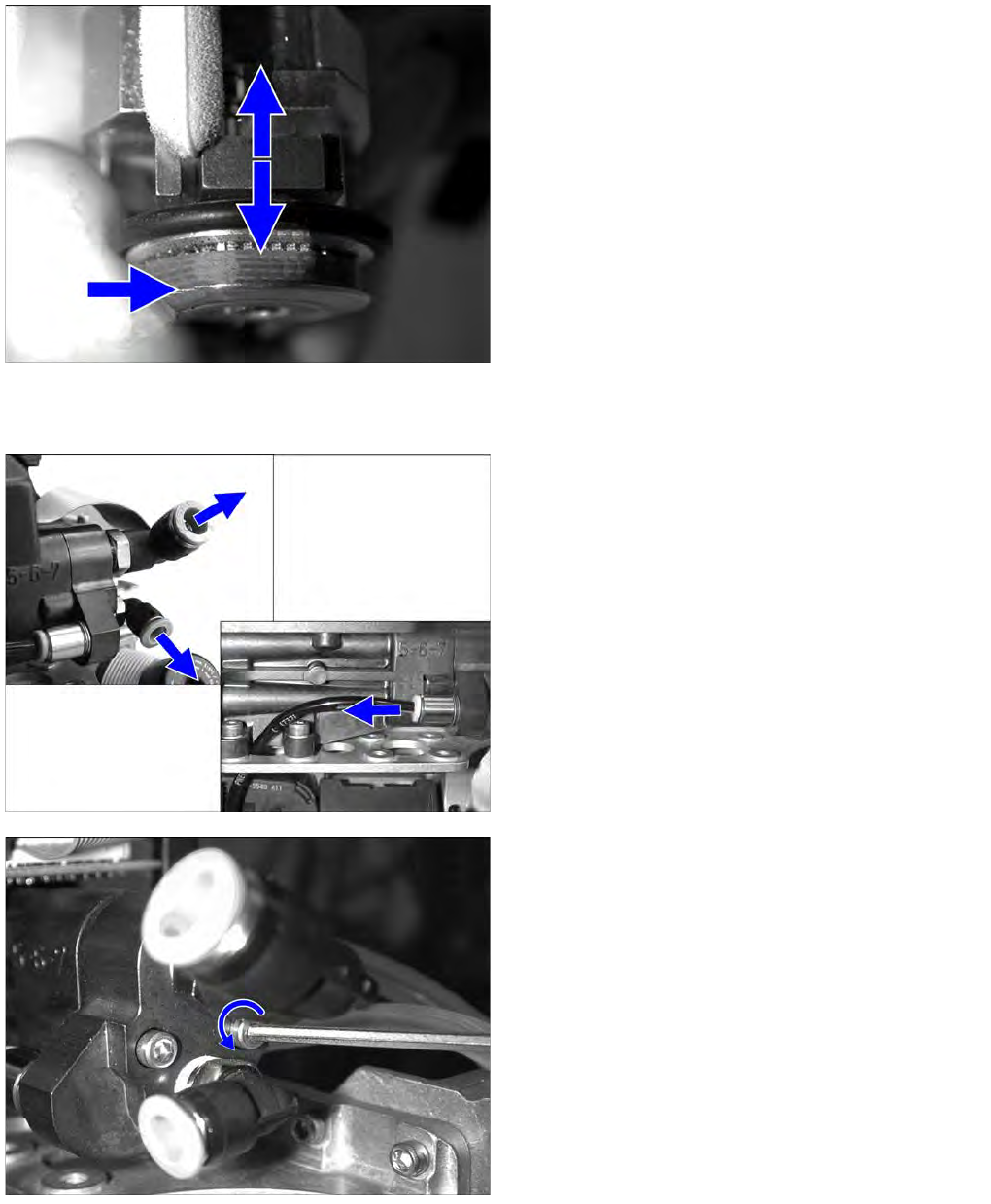
► Press the friction wheel of the turning station against
the spring.
► Clean the stop surfaces using a cottonwool bud
moistened with ethanol.
► Detach the vacuum generator hoses.
► Loosen the two screws (Inbus 2.5 mm) fastening the
vacuum generator block with the 2 vacuum nozzles
(Venturi nozzles).
► Remove the vacuum nozzles.
Major Maintenance
Maintenance Tasks for C&P6/12 Head Performing Maintenance Tasks
114 Maintenance Manual SIPLACE X Series
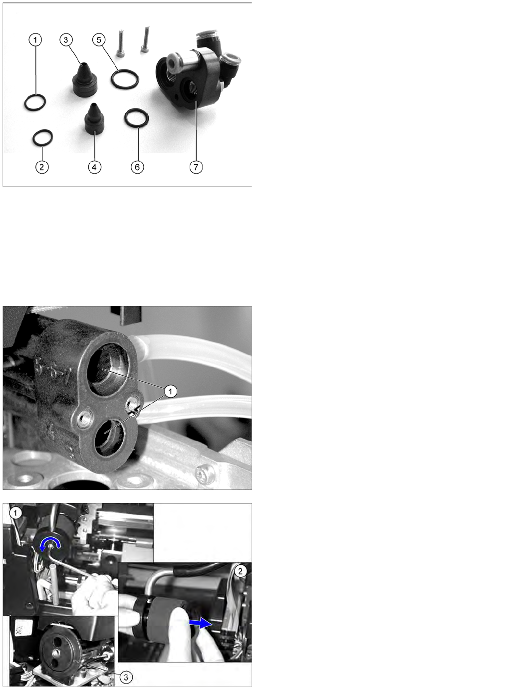
► Carefully clean the vacuum nozzles with a lint-free cloth moistened with ethanol.
► Blow through the vacuum nozzles with compressed air.
► Clean the O-rings with a dry lint-free cloth (replace if necessary).
► Lightly grease the O-rings of the vacuum nozzles with UNISILKON L250L.
► Clean the vacuum generator block using a cottonwool bud moistened with ethanol.
► Place the cleaned parts of the vacuum generator on a clean surface.
► Fit the vacuum generator and silencer. Follow the removal instructions in reverse order for
installation. Also observe the following instructions:
1. O-ring 10*1 Viton 75 [00350662-xx]
2. O-ring 8*1 Viton 75 [00350661-xx]
3. Vacuum nozzle diameter 1.5 [00319420-xx]
4. Vacuum nozzle diameter 1.0 [00319423-xx]
5. O-ring 14*1,5 NBR 70 B [00320048-xx]
6. O-ring 10*1,5 NBR 70 B [00320047-xx]
7. Vacuum generator block
► Clean the drilled holes (1) to the vacuum nozzles with
a cleansing nozzle moistened with ethanol.
Check or replace the silencer on the vacuum generator.
► (1) Loosen the screw used to fix the C&P head
silencer.
► (2) Check the silencer for dirt. If the silencer shows
discoloration, remove it and replace it with a new one.
► Clean the O-ring (3) [00343022-xx] with a dry lint-free
cloth and then grease slightly with UNISILKON
L250L. If the O-ring is damaged, replace it.
► Check the plastic fixtures for the silencer for cracks or
other damage. If the fixtures are defective, replace
the silencer. For removal and installation details, read
the service manual for the respective machine.