X-Series-Maintenance-Manual(1).pdf - 第115页
Major Maintenance Performing Maintenance Tasks Maintenance Tasks for C&P6/12 Head Maintenance Manual SIPLACE X Series 115 Component s ensor (only DLM3) 5.7.3.9 Component sensor (only DLM3) CAUTION Installation instru…
Major Maintenance
Maintenance Tasks for C&P6/12 Head Performing Maintenance Tasks
114 Maintenance Manual SIPLACE X Series
► Carefully clean the vacuum nozzles with a lint-free cloth moistened with ethanol.
► Blow through the vacuum nozzles with compressed air.
► Clean the O-rings with a dry lint-free cloth (replace if necessary).
► Lightly grease the O-rings of the vacuum nozzles with UNISILKON L250L.
► Clean the vacuum generator block using a cottonwool bud moistened with ethanol.
► Place the cleaned parts of the vacuum generator on a clean surface.
► Fit the vacuum generator and silencer. Follow the removal instructions in reverse order for
installation. Also observe the following instructions:
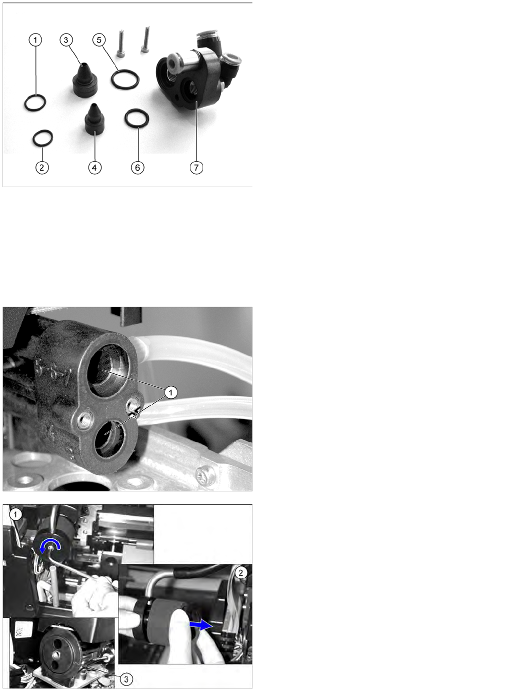
1. O-ring 10*1 Viton 75 [00350662-xx]
2. O-ring 8*1 Viton 75 [00350661-xx]
3. Vacuum nozzle diameter 1.5 [00319420-xx]
4. Vacuum nozzle diameter 1.0 [00319423-xx]
5. O-ring 14*1,5 NBR 70 B [00320048-xx]
6. O-ring 10*1,5 NBR 70 B [00320047-xx]
7. Vacuum generator block
► Clean the drilled holes (1) to the vacuum nozzles with
a cleansing nozzle moistened with ethanol.
Check or replace the silencer on the vacuum generator.
► (1) Loosen the screw used to fix the C&P head
silencer.
► (2) Check the silencer for dirt. If the silencer shows
discoloration, remove it and replace it with a new one.
► Clean the O-ring (3) [00343022-xx] with a dry lint-free
cloth and then grease slightly with UNISILKON
L250L. If the O-ring is damaged, replace it.
► Check the plastic fixtures for the silencer for cracks or
other damage. If the fixtures are defective, replace
the silencer. For removal and installation details, read
the service manual for the respective machine.
Major Maintenance
Performing Maintenance Tasks Maintenance Tasks for C&P6/12 Head
Maintenance Manual SIPLACE X Series 115
Component sensor (only DLM3)
5.7.3.9 Component sensor (only DLM3)
CAUTION
Installation instructions
► Carefully screw the vacuum generator block with the vacuum nozzles tight.
► Before the Venturi nozzles are refitted with the O-rings, make sure that the ethanol has
evaporated completely. If this is not the case, the O-rings could be dissolved over time by
the ethanol.
CAUTION
► Take care not to damage the component sensor prisms.
► Make sure that you do not use the cottonwool buds soaked in oil from cleaning the sleeves.
Always use a new cottonwool bud!
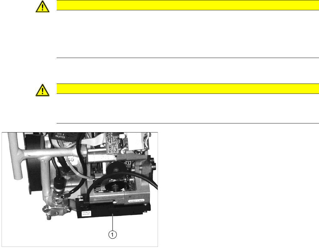
► Clean the prisms of the component sensor with a
cottonwool bud soaked in ethanol.

Major Maintenance
Maintenance Tasks for C&P6/12 Head Final Work
116 Maintenance Manual SIPLACE X Series
Final Work
5.7.4 Final Work
Fitting the front section of the head
► Insert the two O-rings into the back part of head.
► Carefully insert the distributor into its seat.
► Turn the placement star half a step (C&P6: 30°, C&P12: 15°), fit the front part of the head and screw
tight.
► Attach the ribbon cables to the appropriate connectors.
► Insert cleaned or new sleeves into the segments.
► Insert cleaned or new valve plungers into the valve casings.
Fitting the placement head
► Fit the placement head back onto the gantry. Read the service manual for the respective machine
first.
► Switch the placement machine on at the main switch.
► Let the placement head take up the nozzles again.
Test placement:
► The distance between the component camera and the PCB camera can be changed by separating
the front and back parts of the head.
► Carry out a test placement run to test whether the placement accuracy is still guaranteed.
► If the placement accuracy is not guaranteed, calibrate the segment offset 2.
CAUTION
The O-rings must not be seated on the distributor, otherwise they may be damaged.