TRS Advanced WB Intel Issue 02.pdf - 第115页
Issue 2, Nov 14 TRS Advanced Maintenance 115 Objective 39: TRA Pitch Adjustment 1. If pitch adjustment is required, ensure the requir ed active surround is fitted. 2. Select Open Cover Commands . 3. Open the printhead fr…
TRS Advanced Maintenance
114
Issue 2, Nov 14
8
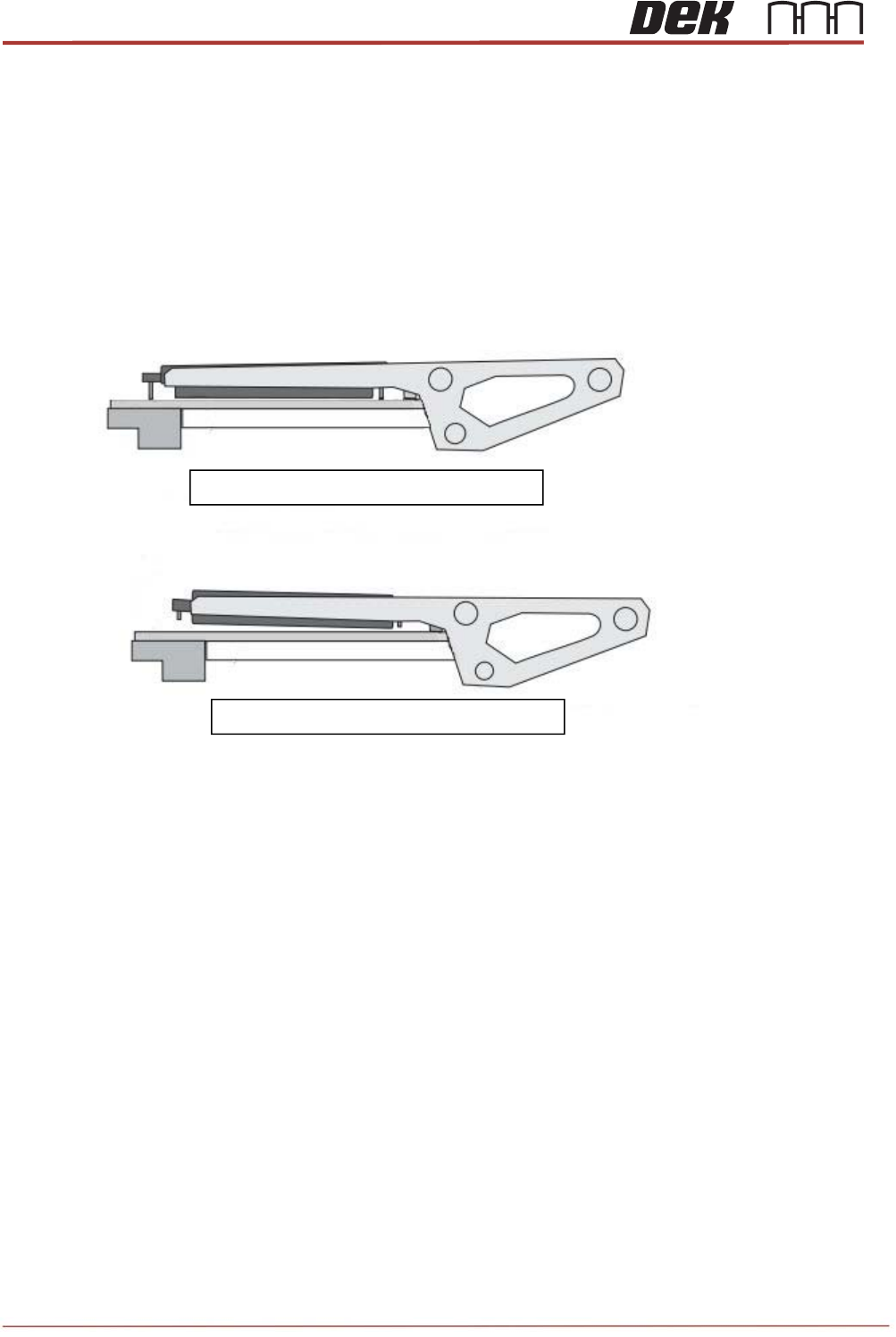
TRP Pitch and Gap set correctly
TRP Pitch and Gap set incorrectly
TRA Pitch and Level Adjustment
To ensure the top reference plate is pulled down level to the active surround and has equal
gap, the TRP pitch and gap must be set-up. If the plate is tilted in any way then this can
result in inconsistent substrate height within the active surround.
Pitch and level adjustment is product specific. Normally, the pitch and level do not need
adjustment but in certain circumstances some adjustment may be required. The need can be
quantified by printing quality checks.
Locate the TRP pitch and gap adjusters on the machine.
9
Issue 2, Nov 14
TRS Advanced Maintenance
115
Objective 39: TRA Pitch Adjustment
1. If pitch adjustment is required, ensure the required active surround is fitted.
2. Select Open Cover Commands.
3. Open the printhead front cover.
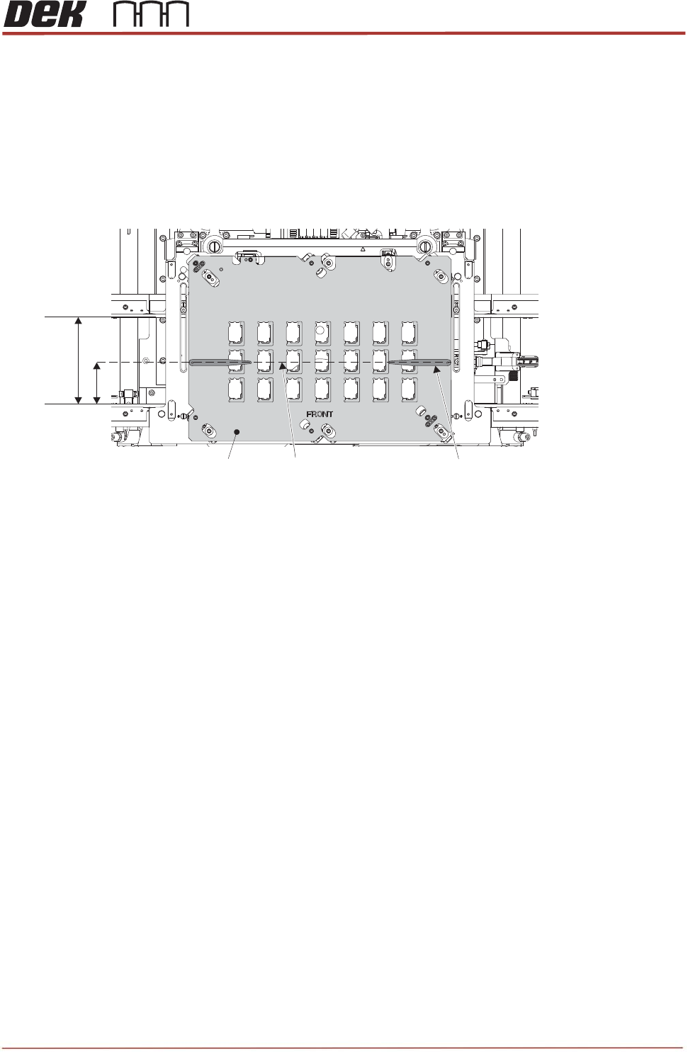
4. On the active surround top plate, measure and mark a pencil line at half the dimensions of the
rails width. Place a pair of 0.4mm shims at either end of the surround plate.
5. Close the printhead front cover.
6. Press the System button.
7. Select Back.
8. Select Back.
9. Select Back.
10. Navigate to the Tooling Setup Page and in the Rising Table section select Transport Height.
Rails Width
Surround Top Plate
Half Width Pencil Line
0.4mm Shim (2 off)
TRS Advanced Maintenance
116
Issue 2, Nov 14
11. In the Top Referencing Section select Over Rails Position.
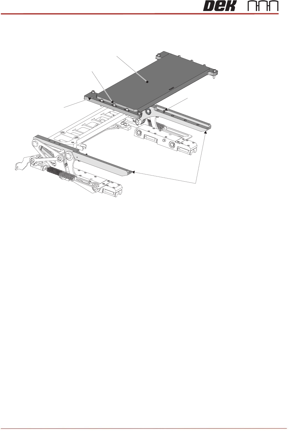
12. Carefully lift the TRP over the tooling area and align the two dowels with the dowel pin alignment
holes on the plate.
13. Lower the TRP onto the arms; tap the four corners to check that it is seated correctly and does not
rock. If the TRP is uneven, the tap sounds sharp. A dull tap indicates correct seating. If there is
rock, investigate the reason before proceeding.
14. Six captive screws secure the TRP to the support arms. By hand, tighten the screws, and using a
calibrated torque setting tool, tighten each screw to a torque of 1.8Nm.
Dowel Pins
(2 off)
Dowel Pin Alignment
Holes (2 off)
TRP Securing
Screws (6 off)
TRP Support Arms
TRP