TRS Advanced WB Intel Issue 02.pdf - 第86页
TRS Advanced Maintenance 86 Issue 2, Nov 14 Pneumatic Schematic 2 (Tooli ng, Active Surround, Z-Lock) T ooling V acuum Z-Lock Circuit V acuum Sense Port in TRS Baseplate Digital Pressure Switch Active Surround and Snugge…
Issue 2, Nov 14
TRS Advanced Maintenance
85
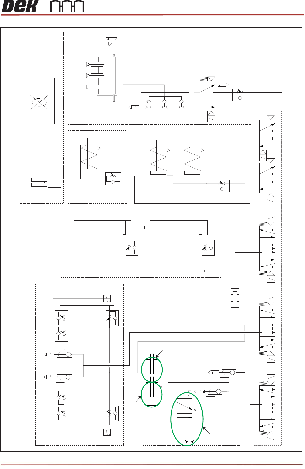
TRS Pneumatic Schematic 1 (TRA-A: TRA-B)
Z-Lock
Cylinder
Z-Lock
Cylinder
Z-Lock
Cylinder
TRA
(Left Hand)
TRA
(Right Hand)
Ref Left
Ref Right
Active Surround Cylinder
Snugger Cylinder (LH)
Snugger Cylinder (RH)
P
High Flow Vaccum To TRS
Tooling Towers
Vacuum Sense
Port In TRS
Baseplate
From Main
Pneumatics Manifold
TRS Board Stop Assembly
From Main
Pneumatics
Manifold
Idle Cylinder
Master Cylinder
Idle Cylinder ON/OFF
Switch
Idle Cylinder ON/OFF
Switch
TRS Advanced Maintenance
86
Issue 2, Nov 14
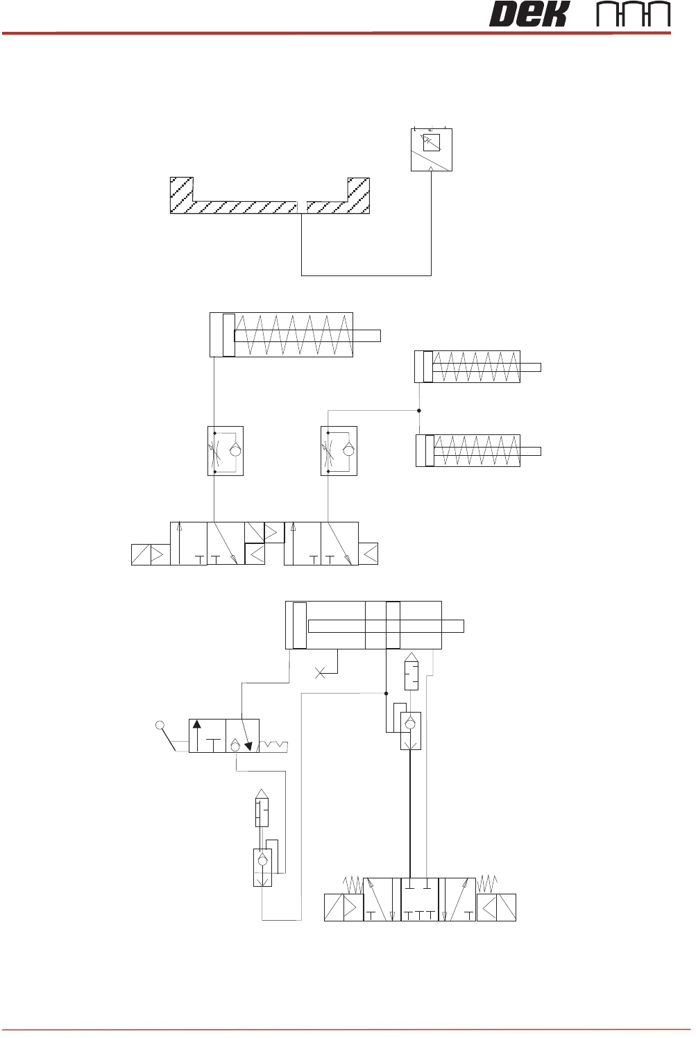
Pneumatic Schematic 2 (Tooling, Active Surround, Z-Lock)
Tooling Vacuum
Z-Lock Circuit
Vacuum Sense Port
in TRS Baseplate
Digital
Pressure
Switch
Active Surround and Snugger Circuit
Z-Lock
Cylinder
Active Surround
Cylinder
Snugger
Cylinder (LH)
Snugger
Cylinder (RH)

Issue 2, Nov 14
TRS Advanced Maintenance
87
1. A pair of pneumatically driven cylinders (TRA-A/B) pulls the yoke forward toward the
tooling area. The pantograph is constrained to move forward and upward simultaneously,
forcing the TRP up and over the surround.
2. At the furthest point of travel, the pair of forked locators engage two reference cylinders,
located at the rear of the rail cap which have risen to the engagement height.
3. The frame is pulled down by the reference cylinders placing the TRP onto the surround.
4. The handler is fed into the print station and secured.
5. The rising table lifts the tooling to vision height. The substrates are compressed against
the TRP, removing substrate warpage.
The pusher plate positions the substrates in the active surround pockets ready for
printing.
NOTE
If the TRP needs additional alignment (to raise it at the back), a pair of pitch adjusters are
on the frame. These provide leverage points at the rear of the TRP. They are set up prior
to printing (see adjustments and settings).
6. Vacuum is applied to ensure surface flatness and prevent substrate movement.
7. The z-lock activates to lock the tooling height (tooling towers only).
8. The reference cylinders vent; a pair of stripper pins located on the frame force the TRP
upwards to give a small amount of clearance.
9. An AND valve in the pneumatic circuit ensures that the lift-off of the TRP is synchronised
with the reference cylinders in the up position.
10. A pair of interlock pins (see section below) are engaged to prevent the pantograph front
arms from lifting too high.
11. The TRA cylinders reverse, pulling the frame down and away from the tooling area. The
TRA disengages from the reference cylinders and lowers in a controlled manner to the
home position at the rear of the printer.
12. The software carries out a vacuum pressure check.
13. The camera is used to capture the fiducials and perform any pre inspection. The camera
withdraws to its home location.
14. The rising table lifts to print height and printing commences.
NOTE
The flow regulators are factory tuned to ensure repeatable results.