TRS Advanced WB Intel Issue 02.pdf - 第70页
TRS Advanced Maintenance 70 Issue 2, Nov 14 7. Loosen (do not remove) the 4 off fixing scr ews on the transport rail spring posts (as shown) 8. With an engineer’s lev el placed in the cent er of the clatter bar , adjust …
Issue 2, Nov 14
TRS Advanced Maintenance
69
Clatter Bar Height Setting;
Clatter bar height setting jig sets the height
from clatter bar to underneath the stencil
mount.
1. Check the height between clatter bar
and underneath the stencil mount.
2. Go to Diagnostics and home the rising
table.
3. Flag the active surround plate present
sensor on the rail cap (top LH) with a
metal feeler gauge.
4. Exit the rising table module*
5. Enter the rising table motor*
*Note
The last two actions are required to
reset the system flag for the active
surround present sensor.
6. Drive the rising table to vision height.
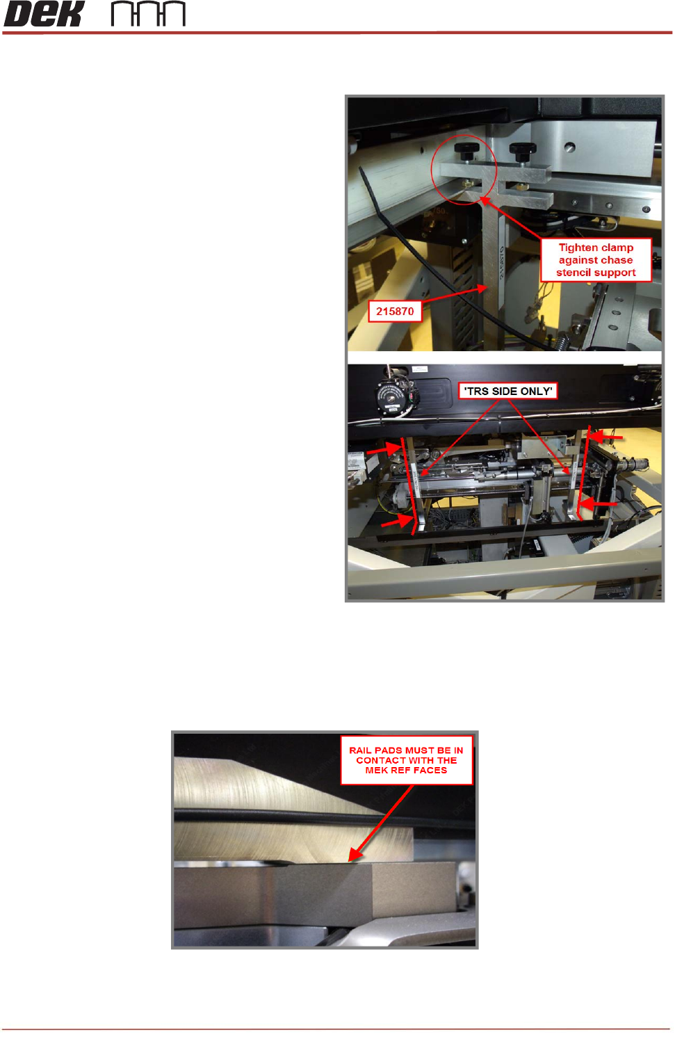
NOTE
Check that the front and rear rail pads are in contact with MEK base.
TRS Advanced Maintenance
70
Issue 2, Nov 14
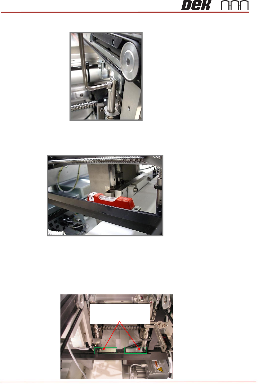
7. Loosen (do not remove) the 4 off fixing screws on the transport rail spring posts (as
shown)
8. With an engineer’s level placed in the center of the clatter bar, adjust one end of the
clatter bar in an upward direction until level.
9. Drive the rising table to print height.
10. Place a 1.0mm setting (feeler) gauge under each of the transport rail spring posts.
Note
The slots in the gauges are positioned under the spring posts.
215713, Note small slots in
the Gauges are concealed
by the Rail Spring Posts

Issue 2, Nov 14
TRS Advanced Maintenance
71
11. Drive the rising table to vision height.
12. Confirm the rail pads are in contact with the MEK base.
13. Confirm that the transport rail spring posts still have some upward movement available.
14. With the transport rail spring posts in contact with the gauges, tighten all 4 off mounting
screws.
15. Drive the rising table to print height and then back to vision height.
16. Check the gap between the setting gauges and the bottom of the clatter bar posts
a 0.05mm feeler should be NOGO.
17. Remove the 4x setting gauges.
18. Tighten the clatter bar mounting nuts and apply Varni-Stop.
19. Confirm the correct operation of the rail lift opto sensors and vane.
20. Remove the metal feeler gauge / shim flagging the surround plate sensor.