TRS Advanced WB Intel Issue 02.pdf - 第52页
TRS Advanced Maintenance 52 Issue 2, Nov 14 38. Undo 3 off M5 cap head screws (do not rem ove the screws) from front rail suppo rt pad and push the support pad upwa rds as far as it will go and tighten the 3 off M5 cap h…
Issue 2, Nov 14
TRS Advanced Maintenance
51
35. Press the rail cap flat and tighten the 6 off M5x16 cap head clamping block screws to
lock alignment bearing guide rods into position as shown below.
36. Press the Rail Cap flat and secure in the locations shown below using:
• 4off M4 x 25 Pan hd screws (700075)
• 2off M4 x 8 Sltd C/snk screws (700405)
• 2off M4 x 16 Pan hd screws (700045)
• 6off M4 crinkle washers (700610)
37. Fully tighten the fasteners before loosening them all by ½ turn.
M4x8 Countersunk
Screws
M4x8 Countersunk
Screws
M4x25 Pan Head Screws
(4 Positions)
M4x16 Pan
Head Screws
M4x16 Pan
Head Screws
View on Rail Cap Assembly
TRS Advanced Maintenance
52
Issue 2, Nov 14
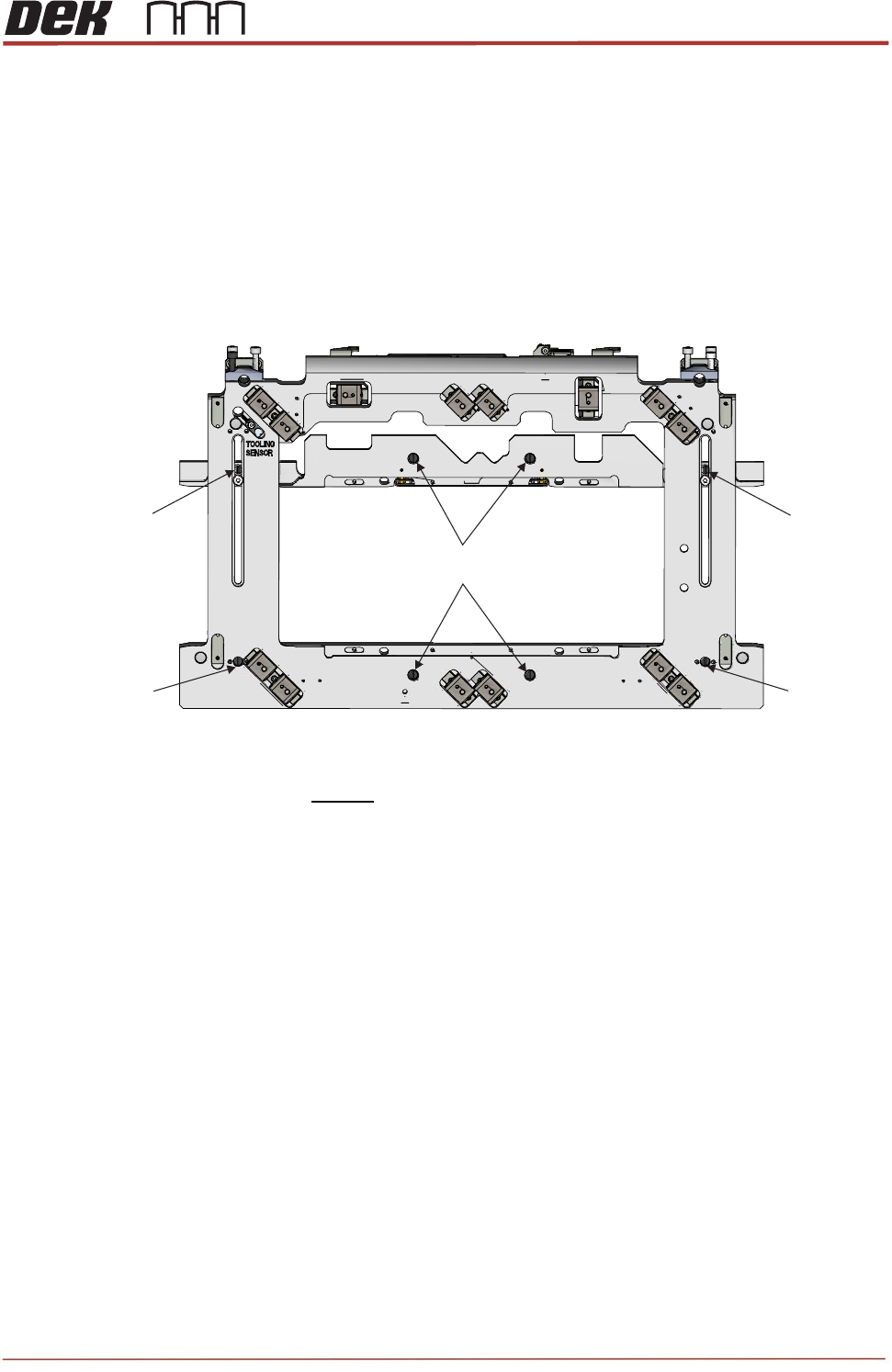
38. Undo 3 off M5 cap head screws (do not remove the screws) from front rail support pad and
push the support pad upwards as far as it will go and tighten the 3 off M5 cap head screws.
39. Repeat the previous step for the rear rail support pad.
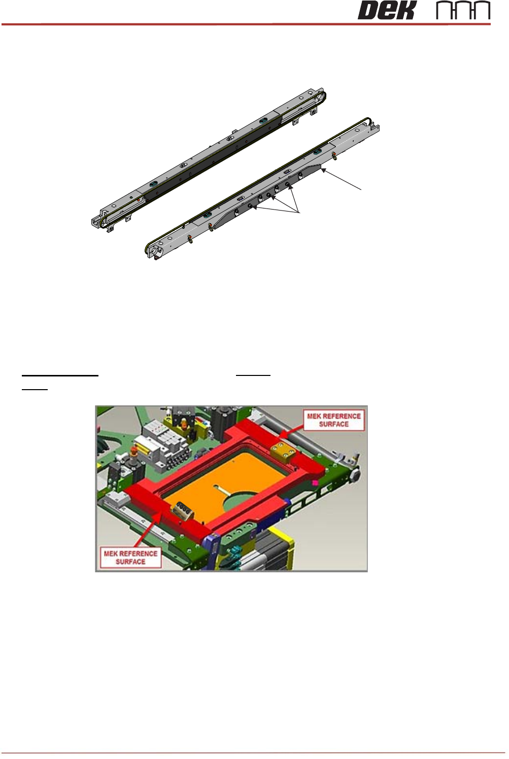
40. Lift the rail cap / rails slightly and place four height setting pins (212276) on the MEK
reference surfaces.
IMPORTANT: The top face of each pin MUST contact the underside of the Rail Cap and
NOT the face of either of the long bearing rails.
M5x12 Cap Head Screws
Front Rail Support Pad
View on Centre Section of the Transport Rails
Issue 2, Nov 14
TRS Advanced Maintenance
53
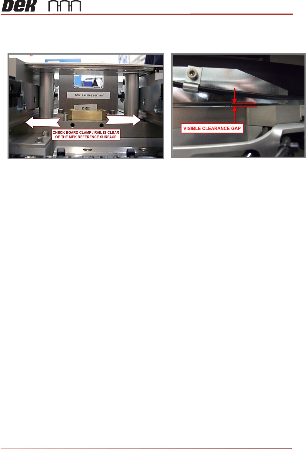
41. With the pins fitted under the rail cap check that a gap exists between the board clamp /
rail and the MEK reference surfaces across the whole assembly.
42. Push the front rail into contact with the buttons of the Rail Alignment Jig (RAJ).