TRS Advanced WB Intel Issue 02.pdf - 第125页
Issue 2, Nov 14 TRS Advanced Maintenance 125 Objective 42: Baseline Data Information Reference information: Both the machine serial number and tooling image number is identifiable in the ASM Merlin Database. Machine Crit…
TRS Advanced Maintenance
124
Issue 2, Nov 14
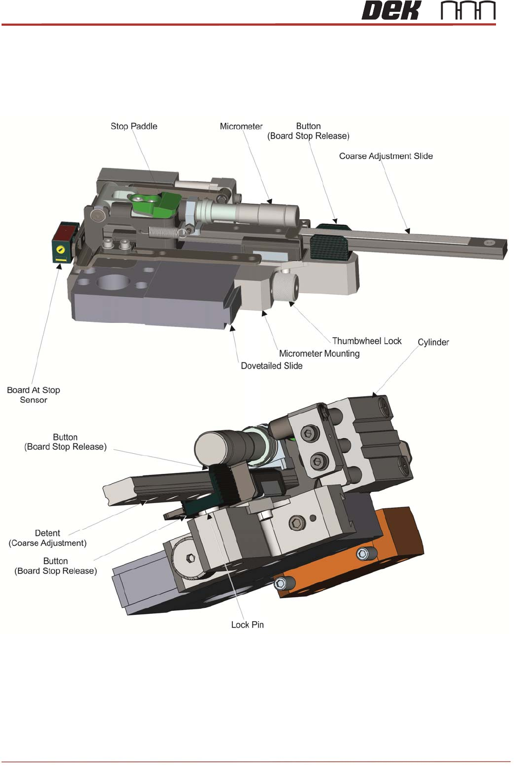
Objective 41: Complete Board Stop Setup as per Product Changeover Procedure in the
EX Technical Reference Manual
Issue 2, Nov 14
TRS Advanced Maintenance
125
Objective 42: Baseline Data Information
Reference information: Both the machine serial number and tooling image number is
identifiable in the ASM Merlin Database.
Machine Critical Information
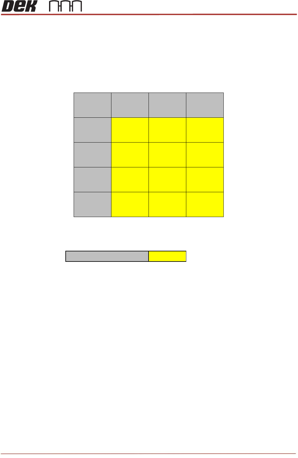
- Rail to Chase cap co-planarity: Record TB384 measurements.
Reading1 Reading2 Reading3
A
B
C
D
- Vacuum Base Capability: With the RAJ fitted and the vacuum flow open toggle the
vacuum on and note the systems total pressure.
Totalvacuumpressure
- Rail Speeds: Complete rail speed calibration for center rails and auxiliary rails and
record values.
Pre Set-up Checks
- Before set-up please confirm that you have access to fresh tray and substrates
- Each substrate must have die attached and preferably un-broken
- Please measure each substrate dimensions X, Y, Z, checking for consistency

TRS Advanced Maintenance
126
Issue 2, Nov 14
Using Tooling Setup Page:
• Visually check the vacuum adaptor plate before fitting for any damage or
contamination
• Fit vacuum adaptor plate and check that is sits against the vacuum seal with no
rocking
• Visually chack the tooling before fitting for any damage or contamination
• Check that tooling is fastened correctly and no rocking can be observed in the tooling
base
• Check with Z-Lock off that all towers move freely in Z
• With Z-Lock ON check that no towers move in Z without considerable force
• Visual check only that all tower caps rotate and return to centre
Warning; Small movements only: over stressing this system will cause damage
Z-Lock Pressure
Aim: To measure the force needed to overcome the Z-Lock pressure
Method: In Diagnostics drive table to Vision Height and lock the Z-Lock in position. Do not
set TRP position. Drive the table to Print Reference Height. Position the Co-Planarity Bars
over the tooling.
Jog the table down using jog buttons until a gap of 3mm to 5mm can be observed between
the bottom of the force meter and the top of the Bars when positioned over the tower.
Apply pressure until the tower moves and the force meter contacts the bars.
Take reading and record in to table below, take 4 reading per tower.
Note: Looking for more than 2Kg per tower. Spring Pressure
Aim: To measure the spring force for per tower, looking for consistency.
Method: In Diagnostics drive table to vision height: Do not set TRP position.
Turn Z-Lock off and make sure the towers move in Z height.
Drive table to print reference height
Position the Co-Planarity bars over the tooling
Jog the table down using jog buttons until a gap of 3mm to 5mm can be observed between
the bottom of the force meter and the top of the bars when positioned over the tower
Apply pressure until the tower moves and the force meter contacts the bars
Take reading and record in to table