TRS Advanced WB Intel Issue 02.pdf - 第116页
TRS Advanced Maintenance 116 Issue 2, Nov 14 11. In the Top Referencing Section select Over Rails Position . 12. Carefully lift the TRP over the tooling area and align the two dowels with the dowel pin alignment holes on…
Issue 2, Nov 14
TRS Advanced Maintenance
115
Objective 39: TRA Pitch Adjustment
1. If pitch adjustment is required, ensure the required active surround is fitted.
2. Select Open Cover Commands.
3. Open the printhead front cover.
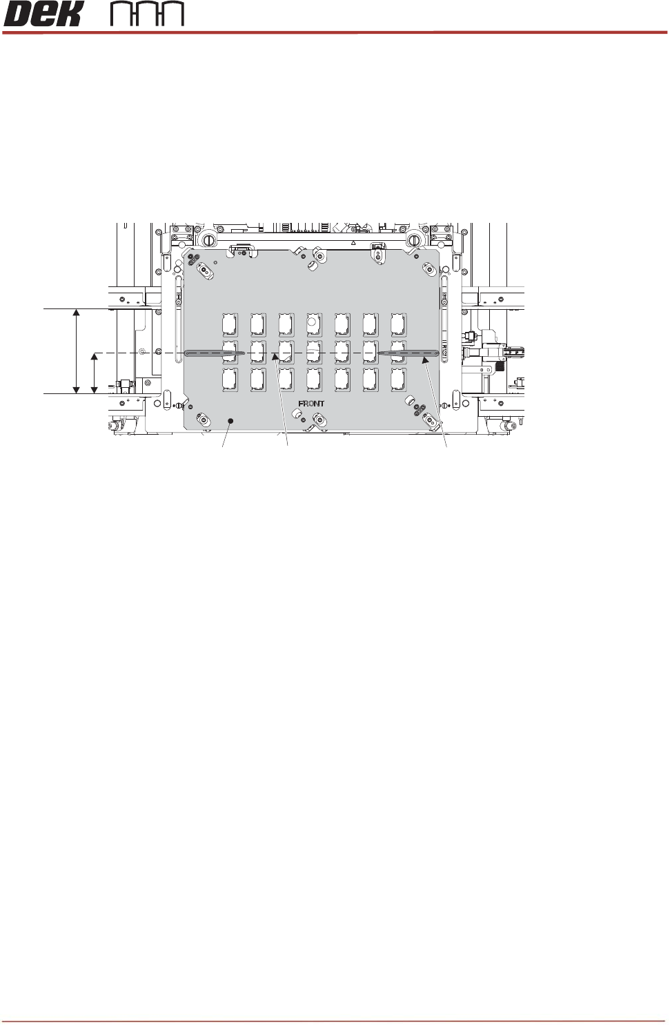
4. On the active surround top plate, measure and mark a pencil line at half the dimensions of the
rails width. Place a pair of 0.4mm shims at either end of the surround plate.
5. Close the printhead front cover.
6. Press the System button.
7. Select Back.
8. Select Back.
9. Select Back.
10. Navigate to the Tooling Setup Page and in the Rising Table section select Transport Height.
Rails Width
Surround Top Plate
Half Width Pencil Line
0.4mm Shim (2 off)
TRS Advanced Maintenance
116
Issue 2, Nov 14
11. In the Top Referencing Section select Over Rails Position.
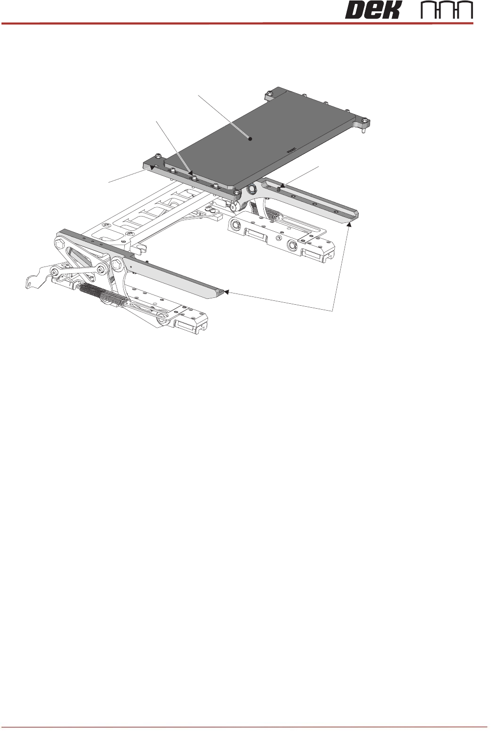
12. Carefully lift the TRP over the tooling area and align the two dowels with the dowel pin alignment
holes on the plate.
13. Lower the TRP onto the arms; tap the four corners to check that it is seated correctly and does not
rock. If the TRP is uneven, the tap sounds sharp. A dull tap indicates correct seating. If there is
rock, investigate the reason before proceeding.
14. Six captive screws secure the TRP to the support arms. By hand, tighten the screws, and using a
calibrated torque setting tool, tighten each screw to a torque of 1.8Nm.
Dowel Pins
(2 off)
Dowel Pin Alignment
Holes (2 off)
TRP Securing
Screws (6 off)
TRP Support Arms
TRP
Issue 2,
15. Ba
c
any
16. Clo
s
17. Pre
s
18. Sel
e
19. Sel
e
20. Op
e
21. Pre
p
Nov 14
c
k off the t
w
adjustmen
t
s
e the front
s
s the Sys
t
e
ct Apply
T
e
ct Open
C
e
n the print
h
p
are the T
R
T
Camera S
a
w
o pitch adj
u
t
.
printhead
c
t
em button.
T
RS Press
u
C
over Com
m
h
ead front
c
R
P jig (POJ
)
T
RP Jig (PO
J
a
fety Guard
u
sters (one
c
over.
u
re.
m
ands.
c
over.
)
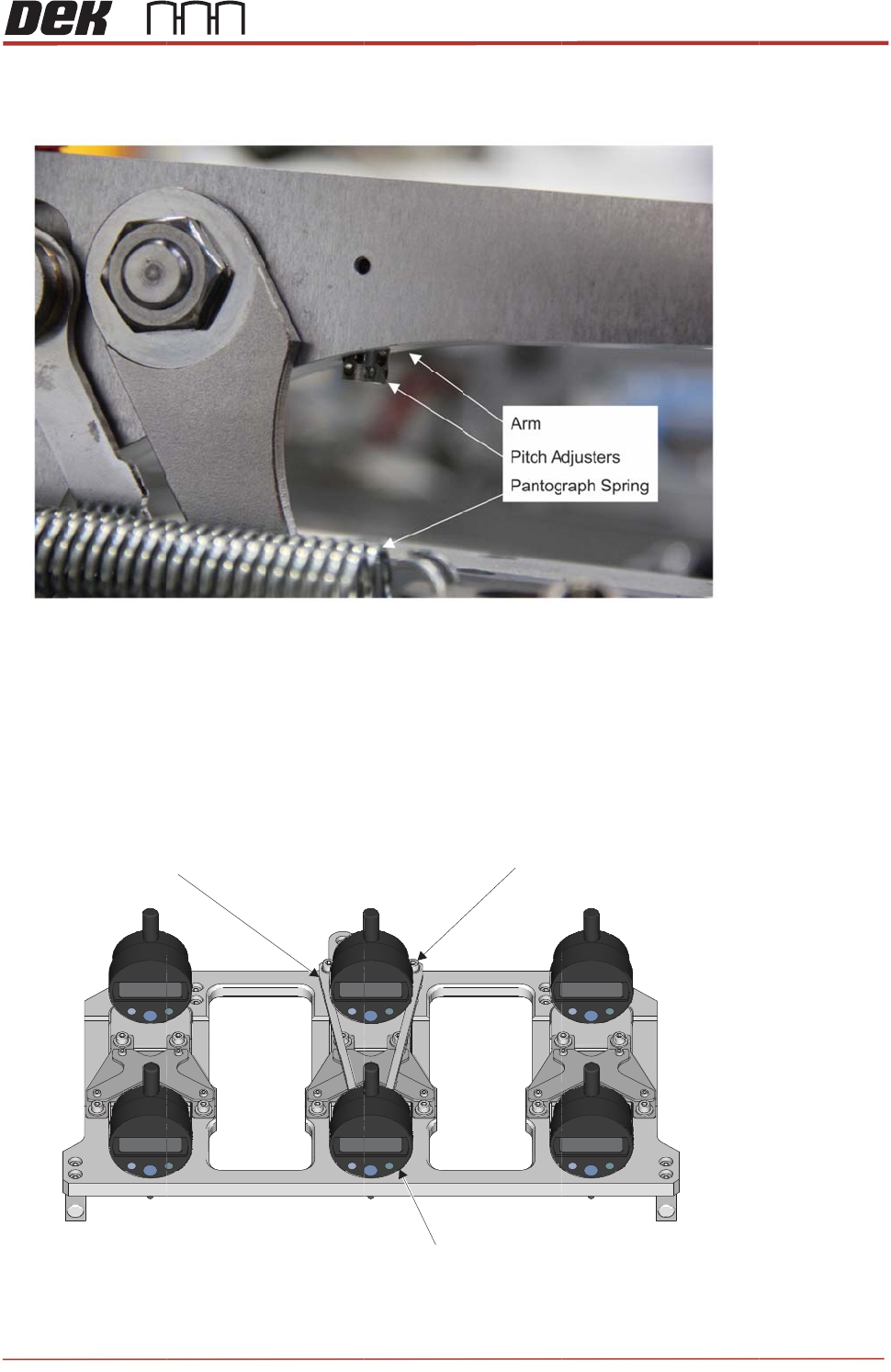
for install
a
J
) with Safet
y
per TRP a
r
a
tion:
y
Guard in St
o
Di
g
r
m), till the
y
owed Positio
gital Dial Test I
Came
Secur
T
R
y
are flush
w
n
I
ndicators (6
o
e
ra Safety Gu
a
r
ing Screws (
2
R
S Advanc
e
w
ith the ar
m
o
ff)
a
rd
2
off)
e
d Maintena
11
7
m
s before s
t
nce
7
t
arting