TRS Advanced WB Intel Issue 02.pdf - 第43页
Issue 2, Nov 14 TRS Advanced Maintenance 43 3. Subtract 1.2mm from the measured gap values above to determine the feeler gauge thickness required in each location to ac hieve the correct gap and height setting. NOTE Usin…
TRS Advanced Maintenance
42
Issue 2, Nov 14
Carry out the following;
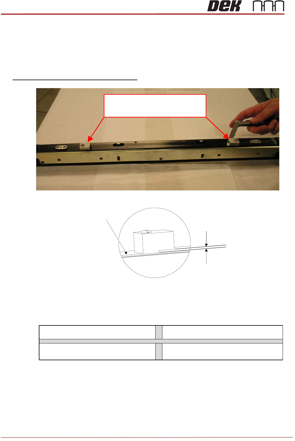
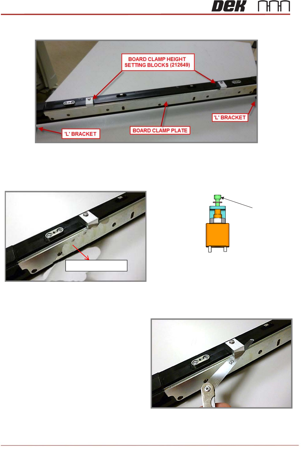
1. Fit 2x board clamp height setting blocks (212649) on to the center section front rail at the
locations shown the picture below.
2. Rotate the blocks inward, gaps facing in and tighten the attached captive screws.
Record the measured gap values here:
Rear Left
Rear Right
Front Left Front Right
Only two board clamp height setting blocks are supplied. Set the front rail first then
change over to set rear rail.
Close View on Board Clamp Height Setting Block
Rail Top Face
BOARD CLAMP HEIGHT
SETTING BLOCKS (212649)
Issue 2, Nov 14
TRS Advanced Maintenance
43
3. Subtract 1.2mm from the measured gap values above to determine the feeler gauge
thickness required in each location to achieve the correct gap and height setting.
NOTE
Using an Allen key on M4x8 cap head screw (on the rail clamp adjustment block
assembly), adjust the height of the Board Clamp Plates evenly using the calculated feeler
gauge thicknesses.
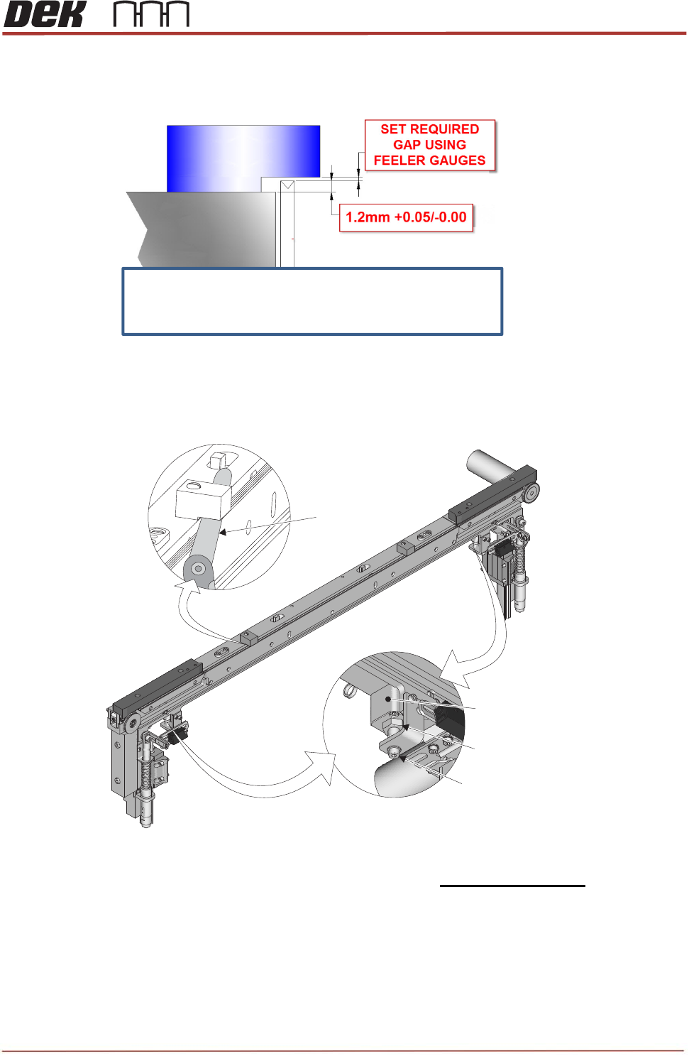
4. The top face of the Board Clamp Plate must be set @ 1.2mm +0.05/-0.00 higher than the
top face of the Centre Rail extrusion.
5. Use the measured gaps above to calculate the correct amount of feeler gauge required
and set the Board Clamp Height to within 0.05mm
Adjustment Block
Lock Nut
Adjustment Screw
View on Rear of Front Central Rail Section
05
Feeler Gauge
Set the board clamp plate height using the
“Rail Cap Adjustment Block Assembly”
TRS Advanced Maintenance
44
Issue 2, Nov 14
6. Rotate both of the Setting Blocks forwards and out over the Board Clamp plate.
7. Using an Allen key on M4x8 cap head screw (on the rail clamp adjustment block
assembly), adjust the height of the Board Clamp Plates evenly using the calculated feeler
gauge thicknesses.
8. Continue fine adjustment until adding a
0.05 gauge makes the gap under each
Setting Block a very tight GO / borderline
NOGO.
View on Rail Clamp Adjustment Block Assembly
M4x8 Cap Head Screw
Board Clam
p
Plate