TRS Advanced WB Intel Issue 02.pdf - 第39页
Issue 2, Nov 14 TRS Advanced Maintenance 39 • Locate the datum edges of the bearing pockets. • Check the bearings are against the datum, using a 0.05mm feeler gauge. It is difficult to check gap between bearing datum edg…
TRS Advanced Maintenance
38
Issue 2, Nov 14
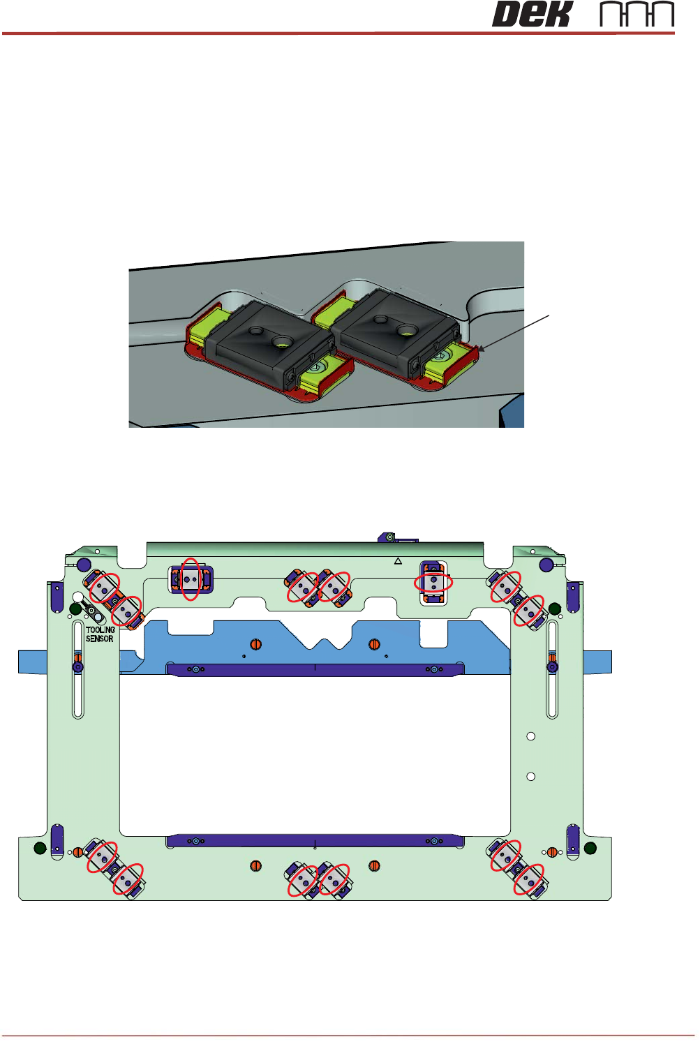
Objective 14: Replacement of the Rail Cap Bearings
• Care should be taking whilst removing the current bearing from the rail cap assembly. Lift
the bearing assembly with the “bearing locating retainer”, damage may occur on the
retainers.
Note
For old design of the rail cap assembly only.
• When fitting the bearings to the rail cap orientate them as shown below:
Bearing Locating
Retainer
Issue 2, Nov 14
TRS Advanced Maintenance
39
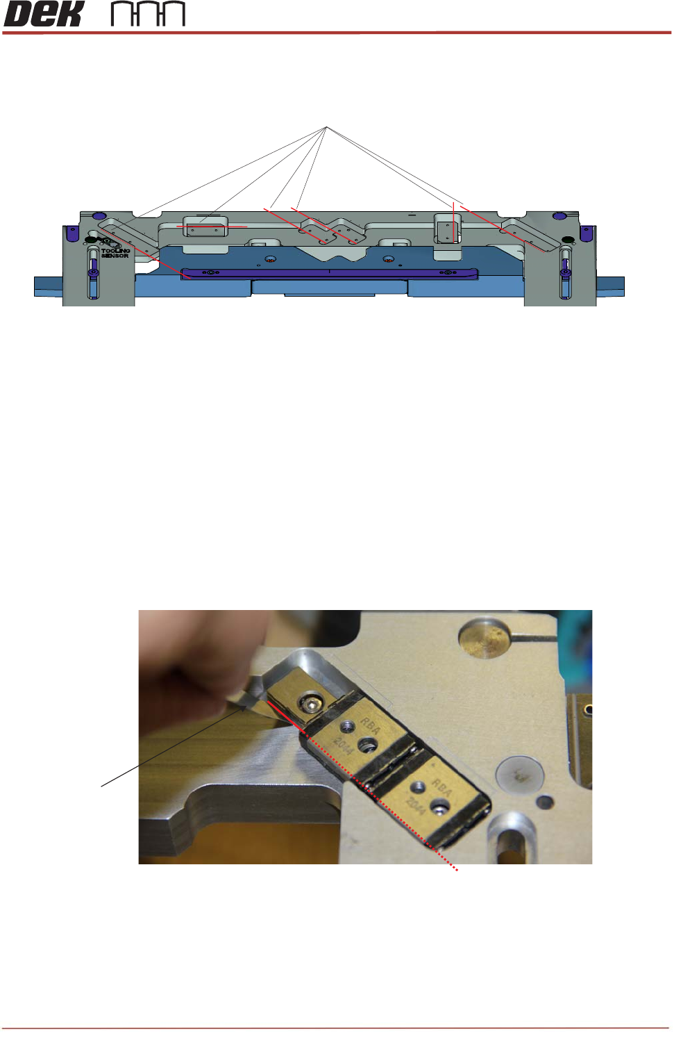
• Locate the datum edges of the bearing pockets.
• Check the bearings are against the datum, using a 0.05mm feeler gauge.
It is difficult to check gap between bearing datum edge and the datum edge on the rail
cap for bearings with “bearing locating retainers”. Make sure that when fitting these
bearings; gently push them towards datum edge without damaging the retainers.
Note
For old design of the rail cap assembly only.
Datum Edges
0.05mm Feeler
Gauge
Datum Edge
TRS Advanced Maintenance
40
Issue 2, Nov 14
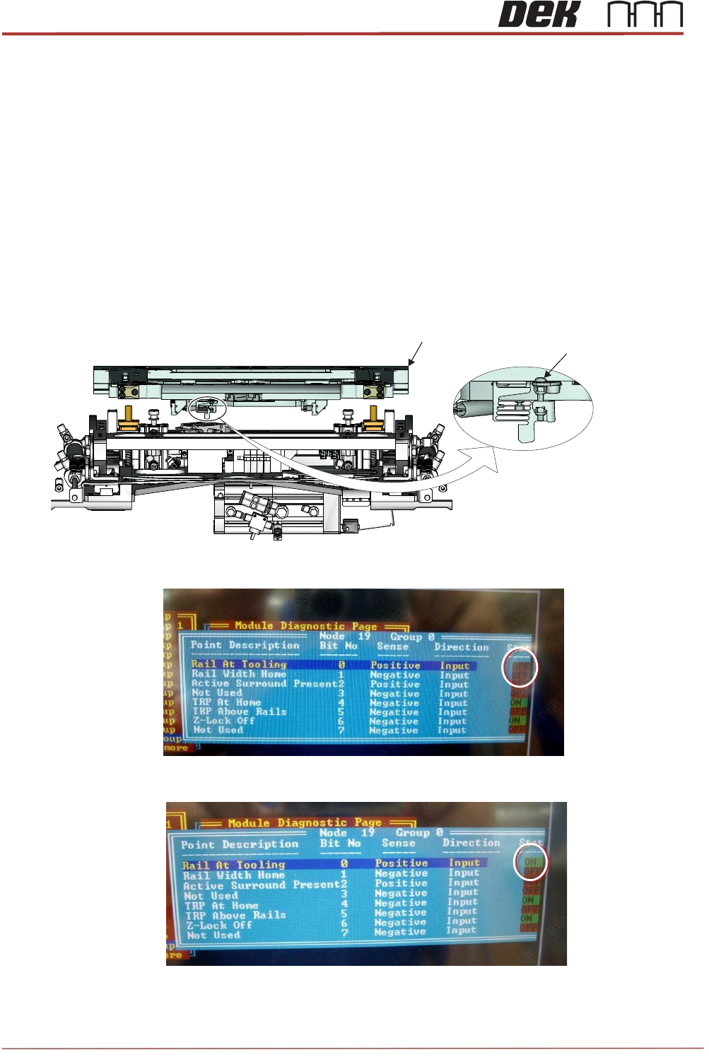
Objective 15: Rail at Tooling (RAT) Vane Setup
Set the RAT vane from the rear of the rail cap assembly, carry out the following:
- In Diagnostics, drive the rising table to VISION Height.
- Go to the System, highlight and select Display All Digital Inputs.
- Select Node 19 Group 0 to set up RAT sensor operation.
- Adjust the RAT sensor vane by adjusting M3x20 button head screw clockwise or anti-
clockwise so that it just triggers the sensor state to OFF in Diagnostics display.
NOTE
When adjusting sensor keep pressure on the screw.
- Rotate the screw anti-clockwise until sensor states just changes to ON.
- Rotate the screw anti-clockwise extra one 1/4 turn.
Viewed from Rear of the TRS Unit
Rail Cap Assembly
M3x20 Button
Head Screw