TRS Advanced WB Intel Issue 02.pdf - 第121页
Issue 2, Nov 14 TRS Advanced Maintenance 121 32. Using a small Allen key, adjust each TRP arm pitch adjuster in turn while watching the gauges. 33. Adjust until an equal dimension over the four gauges (gauges 1, 4, 3 and…
TRS Advanced Maintenance
120
Issue 2, Nov 14
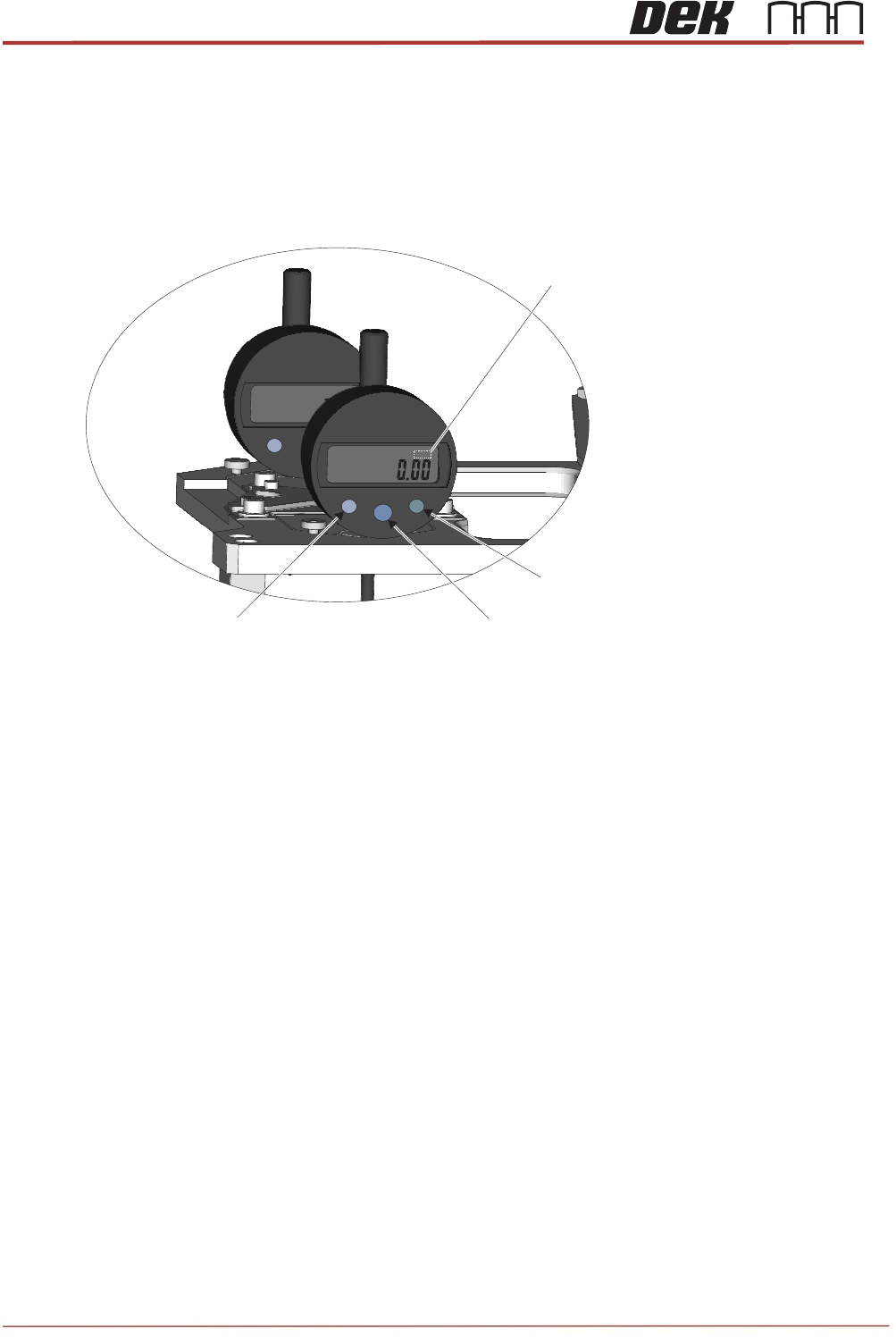
23. Switch on and zero out the four outer gauges (not the central pair):
a. Press the Data button to switch on.
b. Zero the gauge by pressing the Set button.
c. Check that the measurement unit shown on the screen is “mm”. If it is showing “in” press the
Mode button and check the screen has changed to display “mm”.
24. Close the printhead front cover.
25. Press the System button.
26. Select Back.
27. Select Back.
28. Select Back.
29. Navigate to the Tooling Setup Page and in the Rising Table section select Vision Height.
30. Select Open Cover Commands.
31. Open the printhead front cover.
in
.
mm
MODE
SET
DATA
ON
OFF
.
mm
in
mm
MODE
.
Data Button (On/Off)
Set Button (Zero)Mode Button (in/mm)
Measurement Unit
Indicator
Issue 2, Nov 14
TRS Advanced Maintenance
121
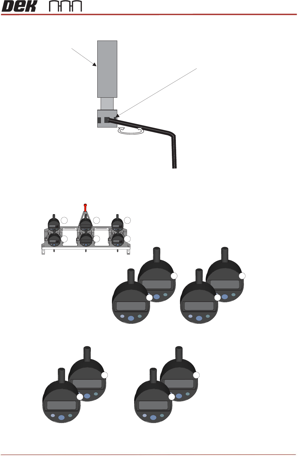
32. Using a small Allen key, adjust each TRP arm pitch adjuster in turn while watching the gauges.
33. Adjust until an equal dimension over the four gauges (gauges 1, 4, 3 and 6) is achieved, to within
a total deviation of no more than 50
μ
.
Insert 1.5mm Allen Key
Pitch Adjuster
Clockwise to lower
mm
mm
mm
mm
1 2
3
4
5
6
POJ Jig Gauge Numbering
Example of equal dimension over the four gauges
(total deviation no more than 50μ)
mm
-0.201
mm
-0.201
1
4
mm
-0.236
mm
-0.230
3
6
Example of “Front Bias”
(Front Gauge of Pair is 150 Greater +/- 10μμ)
mm
-0.108
mm
-0.252
1
4
mm
-0.131
mm
-0.283
3
6
TRS
A
122
34.
O
g
a
a
n
35.
O
36.
R
37.
R
38.
C
39. P
40. S
41. S
42. S
43. S
44. F
s
u
45.
C
c
o
46.
U
fr
o
T
h
47.
U
b
r
A
dvanced
M
O
nce this le
a
uges (gau
g
n
d 3) +/- 10
O
n each ga
u
R
eturn the c
a
R
eturn POJ
j
C
lose the pr
i
ress the S
y
elect Back
elect Back
elect Back
elect Togg
rom the c
o
u
rround.
C
heck if adj
u
o
ntact the r
a
sing a 0.0
5
o
nt and rea
h
e pitch ad
j
sing an 1.
5
r
ing the pla
t
M
aintenanc
e
e
vel has be
ges 4 and
6
0
μ (front bia
s
u
ge, press t
a
mera saf
e
j
ig to its st
o
i
nthead fro
n
y
stem butt
o
.
.
.
le Vacuu
m
o
mmand b
a
u
stment is
a
il cap pad
s
5
mm feeler
r edges. If
a
j
ustment s
c
5
mm
A
llen
t
e down at
t
e
en achiev
e
6
) read a
v
s
).
he Data bu
e
ty guard to
o
rage box.
n
t cover.
o
n.
m
to turn va
c
a
r select A
p
required b
y
s
.
gauge che
c
a
0.05mm
c
c
rews are u
s
key throug
t
he front an
e
d, continu
e
v
alue 150μ
g
t
ton to swit
c
its stowed
c
uum ON.
p
ply TRP
P
y
backing-o
f
c
k the gap
c
an be slid
s
ed to brin
g
h
the hole
s
d wind it in
e
to adjust
greater tha
c
h off. Re
m
position (r
e
P
ressure.
T
f
f the four
h
between th
between th
g
the plate f
s
of the pit
c
to bring th
e
the pitch
a
n their res
p
m
ove the P
O
e
verse of St
e
T
he TRP i
s
h
eight setti
n
e TRP and
e surfaces
l
at against
t
c
h adjuster
e
plate up.
Issu
a
djusters u
n
p
ective rea
r
O
J jig from t
h
e
p 21).
s
pulled do
n
g screws
u
the active
s
a
djustment
t
he active s
body, wind
u
e 2, Nov 14
n
til the fro
n
r
gauges (
g
he TRP.
o
wn onto t
h
u
ntil they n
s
urround,
a
t
is require
d
s
urround
the adjust
e
n
t pair of
g
auges 1
h
e active
o longer
a
long the
.
e
r out to