TRS Advanced WB Intel Issue 02.pdf - 第72页
TRS Advanced Maintenance 72 Issue 2, Nov 14 Objective 17: Set following on the machine, using Technical Reference Manual, HTC Chapter: NOTE: Make sure machine is level before setting the auxiliaries. Auxiliary Rail to Pr…

Issue 2, Nov 14
TRS Advanced Maintenance
71
11. Drive the rising table to vision height.
12. Confirm the rail pads are in contact with the MEK base.
13. Confirm that the transport rail spring posts still have some upward movement available.
14. With the transport rail spring posts in contact with the gauges, tighten all 4 off mounting
screws.
15. Drive the rising table to print height and then back to vision height.
16. Check the gap between the setting gauges and the bottom of the clatter bar posts
a 0.05mm feeler should be NOGO.
17. Remove the 4x setting gauges.
18. Tighten the clatter bar mounting nuts and apply Varni-Stop.
19. Confirm the correct operation of the rail lift opto sensors and vane.
20. Remove the metal feeler gauge / shim flagging the surround plate sensor.

TRS Advanced Maintenance
72
Issue 2, Nov 14
Objective 17: Set following on the machine, using Technical Reference Manual, HTC
Chapter:
NOTE: Make sure machine is level before setting the auxiliaries.
Auxiliary Rail to Print Station Gap
Auxiliary Conveyor Levelling
Auxiliary Conveyor Front / Rear Rail Parallelism
Auxiliary Conveyor Height Setting
Issue 2, Nov 14
TRS Advanced Maintenance
73
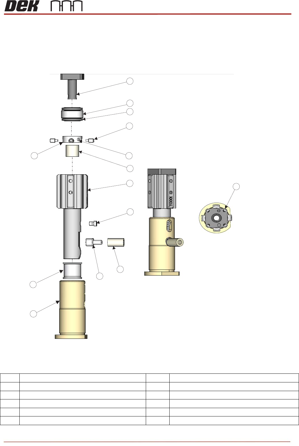
Objective 18: Maintain Tooling Towers
Identify Tooling Tower parts
1 8
2&3 9&10
4 11
5 12
6 13
7
2
4
2
7
6
5
4
3
1
1
8
10
13
2
Exploded View
Tooling Pin Assembly and Lock
View on Top
9
11
12