TRS Advanced WB Intel Issue 02.pdf - 第34页
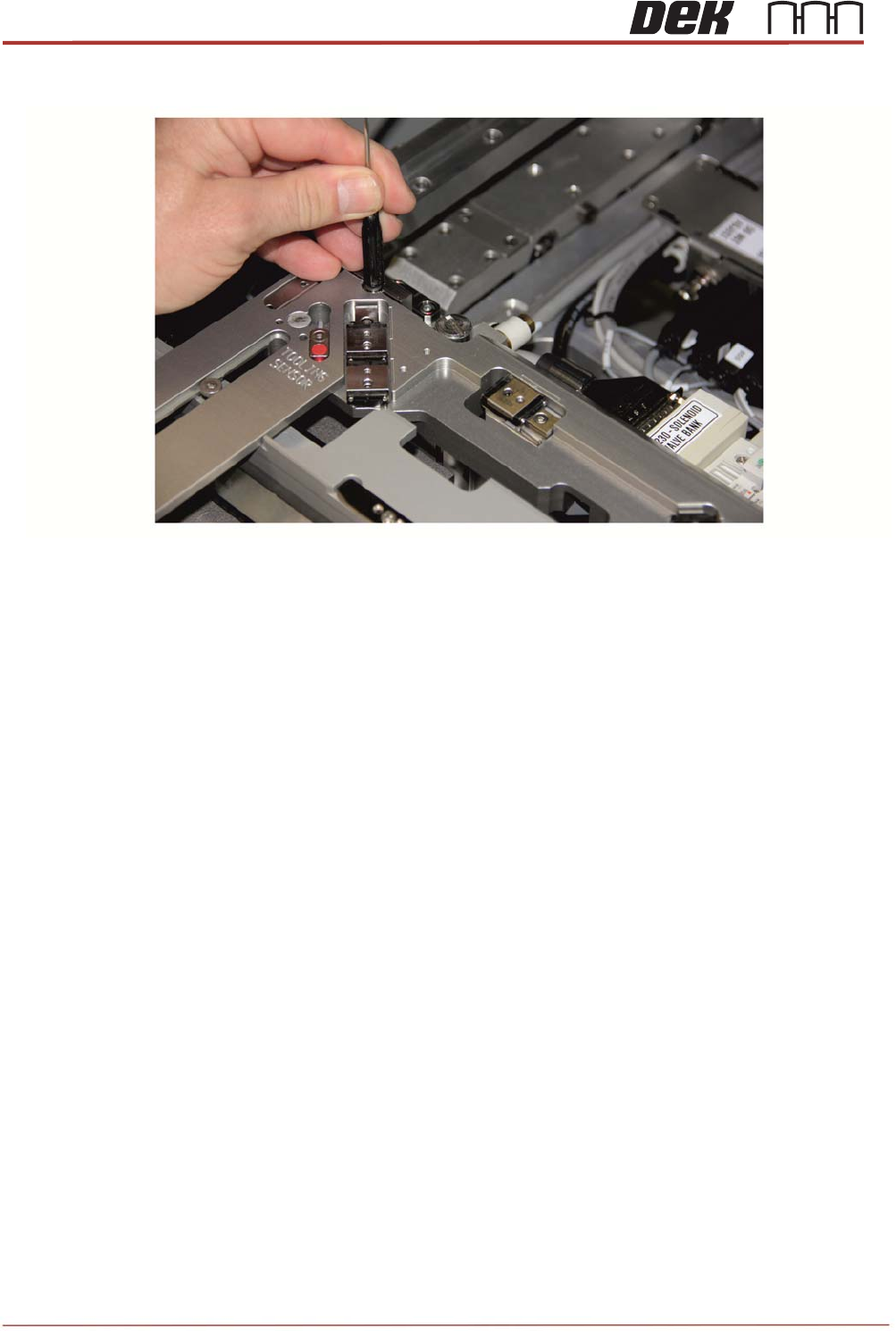
TRS Advanced Maintenance 34 Issue 2, Nov 14 5. Gently tap down each gui de rods until it bottoms out do not go any further.
Issue 2, Nov 14
TRS Advanced Maintenance
33
Fitting the Rail Cap to the Printer
1. Ensure Rising Table is at the print height.
2. Fit the rail cap onto the rails with locating the four locating plates into position and
engage the clamping blocks with the alignment bearing guide rods.
NOTE
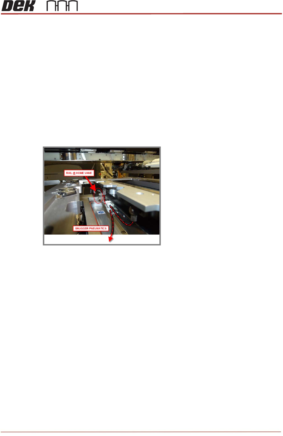
Engage the rail width home sensor vane (on the rear rail) into the sensor (on the rail cap)
without damaging it.
3. Connect the short snugger pipe (on the right side of the rail cap) in to the single inlet of
the “Y” fitting behind the rear rail, as shown below.
4. Connect the other snugger pipe (on the left side of the rail cap) in to the one of the outlet
on the “Y” fitting, as shown above.
NOTE
Make sure they are not stretched or creased.
TRS Advanced Maintenance
34
Issue 2, Nov 14
5. Gently tap down each guide rods until it bottoms out do not go any further.
Issue 2, Nov 14
TRS Advanced Maintenance
35
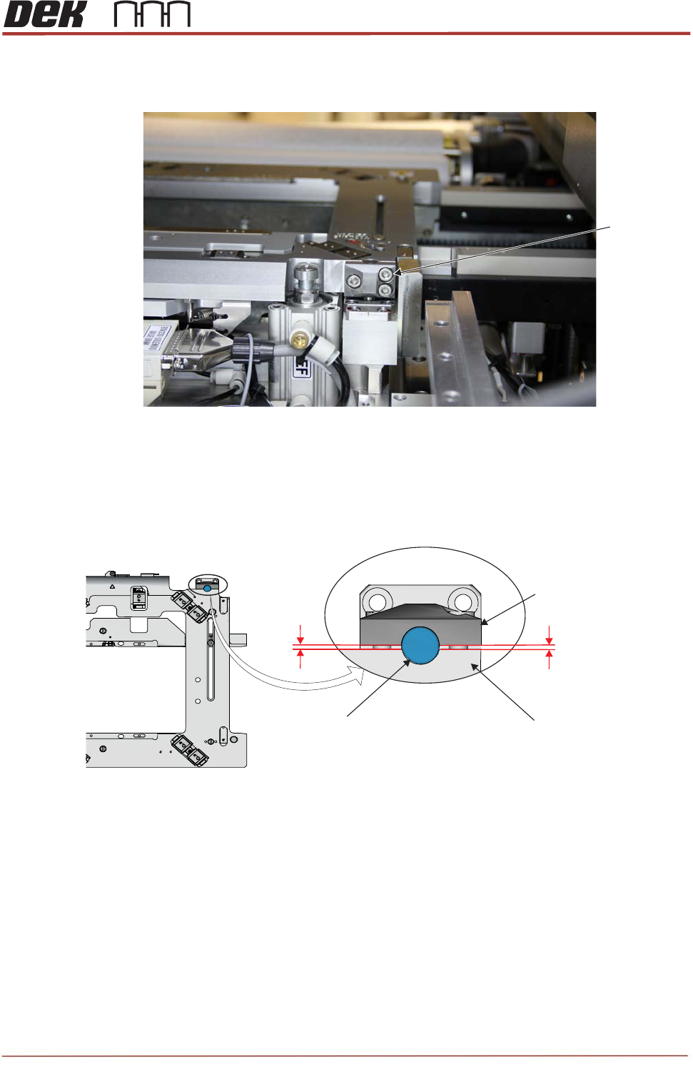
6. Tighten the 6 guide rods locking screws equally (3 for each side of the rail cap) to lock
the guide rods into the position.
NOTE
Ensure there is an even gap between clamping block and the rail cap as shown below.
M5x16 Cap
Head screws
Viewed from the Rear of the Machine
Partial View on Rail Cap Assembly
Clamping Block
Rail Cap
Alignment Bearing
Guide Rod
Gap
Gap