TRS Advanced WB Intel Issue 02.pdf - 第76页
TRS Advanced Maintenance 76 Issue 2, Nov 14 Objective 19: Explain how Z-Lock Mechanism works. Z-Lock cylinders are placed in the space under the base plate and in front of the table casting. This orientation allowed a la…

Issue 2, Nov 14
TRS Advanced Maintenance
75
Notes:
TRS Advanced Maintenance
76
Issue 2, Nov 14
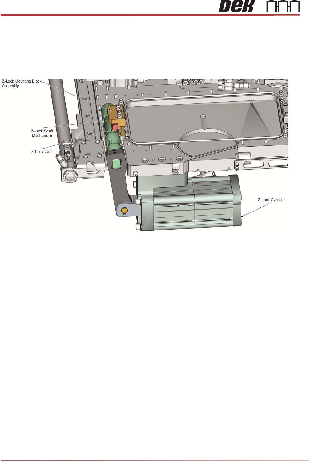
Objective 19: Explain how Z-Lock Mechanism works.
Z-Lock cylinders are placed in the space under the base plate and in front of the table
casting. This orientation allowed a large crank shaft to be supported within the base plate
thickness which was assisted by having a split line to enable a simple construction method.
Although the sliding block (Z-Lock mounting block) material is aluminum bronze, the degree
of friction and wear that can occur with the cam feature is significant. So the cam interface is
assembled with a large amount of grease, as are the plain bearings for the crank shaft.
Issue 2, Nov 14
TRS Advanced Maintenance
77
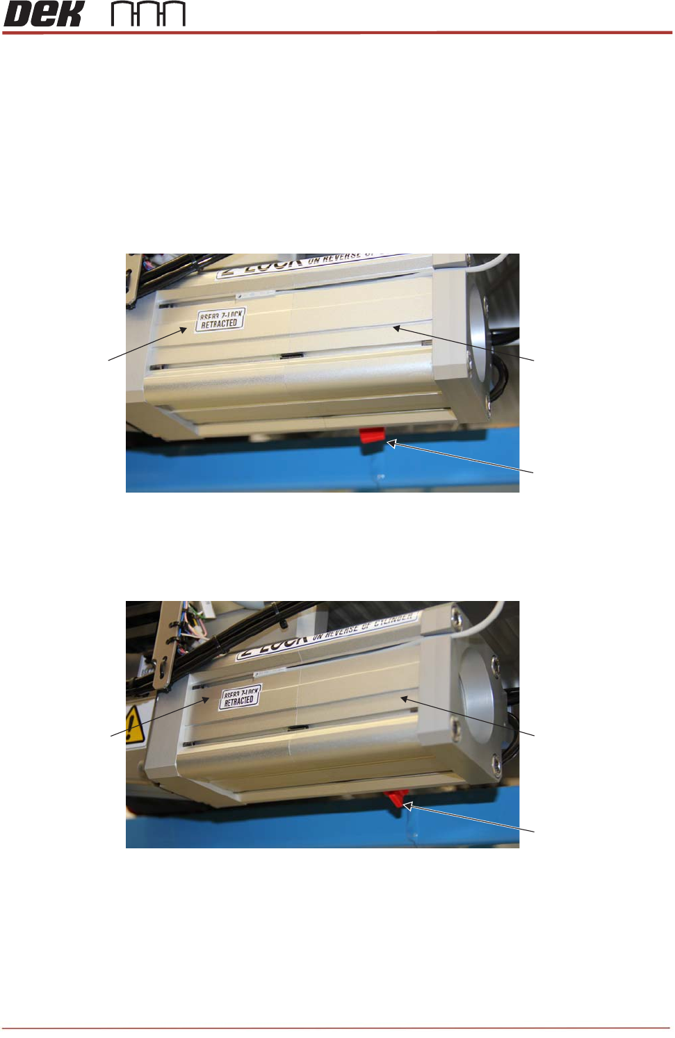
Z-Lock Master and Idler Cylinders
The Z-Lock mechanism requires a large force to achieve sufficient clamping pressure on all
present towers simultaneously.
Maximum applied force (less friction) through the mechanism is 14, 800 N with both Master
and Idler Cylinders are active.
The reduced force generated with just one pneumatic cylinder active (less friction) is: 7,792N
Z-Lock Idler Cylinder
ON/OFF Switch
Master
Cylinder
Idler
Cylinder
View on Z-Lock Cylinders and ON/OFF Switch
(Switch Position Indicates that Idler Cylinder is active)
Master
Cylinder
Idler
Cylinder
Z-Lock Idler Cylinder
ON/OFF Switch
View on Z-Lock Cylinder and Idler Cylinder ON/OFF Switch
(Switch Position Indicates that Idler Cylinder is OFF)