00198628-01_Option_Stationäre-Kamera_TX12_V2_de_en.pdf - 第100页
4 Appendix 4.1 Excerpts from the Service Manual 100 Assembly Instructions / Montageanleitung SIPLACE TX-Series V2 Stationary Camera Type 25/33 Stationäre Kamera Typ 25/33 10/2018 4.1.1 Calibrating the heads and cameras (…

4 Appendix
4.1 Excerpts from the Service Manual
Assembly Instructions / Montageanleitung SIPLACE TX-Series V2 Stationary Camera Type 25/33 Stationäre Kamera
Typ 25/33 10/2018
99
4 Appendix
4.1 Excerpts from the Service Manual
The following chapters are excerpts from the service manual. For more information, refer to the full
service manual for your machine.
4 Appendix
4.1 Excerpts from the Service Manual
100 Assembly Instructions / Montageanleitung SIPLACE TX-Series V2 Stationary Camera Type 25/33 Stationäre Kamera
Typ 25/33 10/2018
4.1.1 Calibrating the heads and cameras (SW70x)
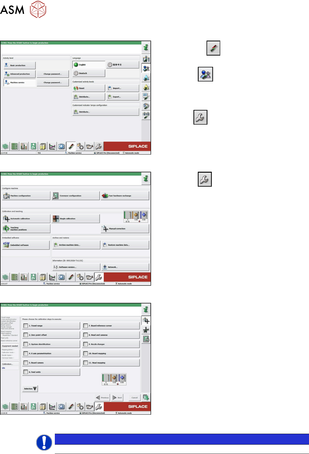
Fig.59: Select operator level
► Click on the button, to open the Configure,
update and calibrate the machine menu.
► Click the button to open the Check and
set user settings menu.
► Switch over to the operator level Machine
service.
ð The button will appear.
Fig.60: Service menu
► Click the button to enter the Service menu.
► Click the Automatic calibration button.
Fig.61: Automatic calibration
► Select Heads and cameras.
► Click on the Continue button.
Follow the instructions on the next pages:
► On the next page, select the gantries on which
the heads to be calibrated are located and then
click on the Next button.
► The next step is to check the calibration condi-
tions (nozzle, calibration tool etc.). Follow the
instructions provided.
After this step, the calibration will begin. All required
intermediate steps (head height etc.) will be performed
automatically.
NOTICE
With station software 712.0, the user interface of the Automatic calibration has changed.
4 Appendix
4.1 Excerpts from the Service Manual
Assembly Instructions / Montageanleitung SIPLACE TX-Series V2 Stationary Camera Type 25/33 Stationäre Kamera
Typ 25/33 10/2018
101
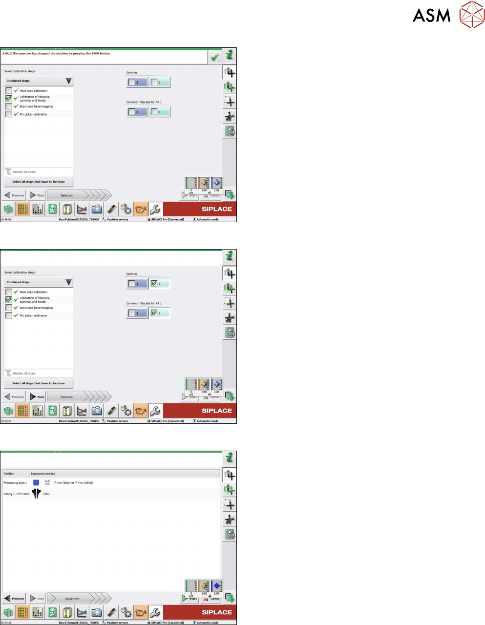
Fig.62: Combined steps view
► On the left-hand side, under Combined steps,
select the check box Calibration of fiducials,
cameras and heads.
► If you selected Display all steps on the left-hand
side, select Calibration of cameras and heads.
► Under Gantries, select the location. For a TX
machine, always location 1.
► Click Next.
Fig.63: Prerequisites view
Prerequisites view.
► Click on Start to start the calibration.
Fig.64: Calibration steps and status view
Calibration steps and status view.