00198628-01_Option_Stationäre-Kamera_TX12_V2_de_en.pdf - 第103页
4 Appendix 4.1 Excerpts from the Service Manual Assembly Instructions / Montageanleitung SIPLACE TX-Series V2 Stationary Camera Type 25/33 Stationäre Kamera Typ 25/33 10/2018 103 4.1.2 Nozzle Changer Setting 4.1.2.1 Sett…
4 Appendix
4.1 Excerpts from the Service Manual
102 Assembly Instructions / Montageanleitung SIPLACE TX-Series V2 Stationary Camera Type 25/33 Stationäre Kamera
Typ 25/33 10/2018
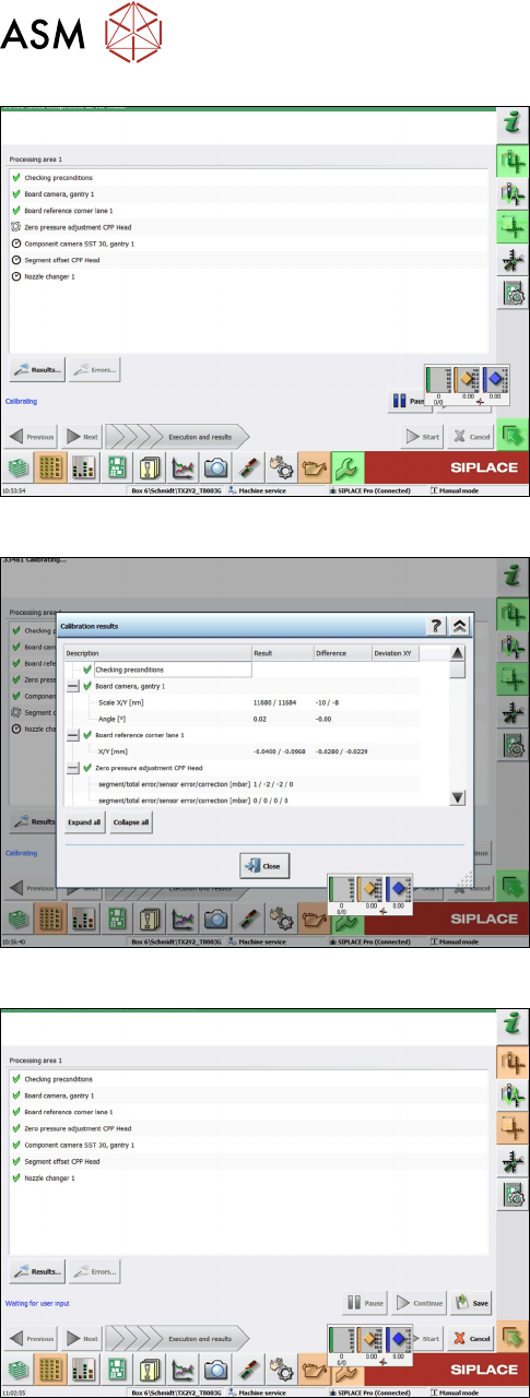
Fig.65: Results view
► Click Results to display detailled information (im-
portant in case of an error).
Fig.66: Save view
► Click Save after successful calibration.
Fig.67: Save button
► Click the Save button.
ð Calibration has finished.
4 Appendix
4.1 Excerpts from the Service Manual
Assembly Instructions / Montageanleitung SIPLACE TX-Series V2 Stationary Camera Type 25/33 Stationäre Kamera
Typ 25/33 10/2018
103
4.1.2 Nozzle Changer Setting
4.1.2.1 Setting the Nozzle Changer Height
Parts, equipment and tools
●
Measuring scale
●
NC shim plate (0.3mm) [03021079-xx]
Overview
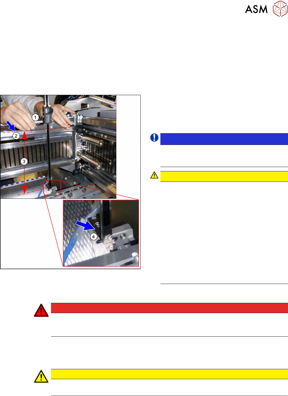
Fig.68: Overview of measurement procedure
1. Measuring scale
2. Top edge of the X axis upper linear guide
3. Values to be set (277 +/- 0.2 mm)
4. Nozzle changer contact surface
NOTICE!
Alternatively, you can measure from the top
edge of the lower guide rail of the gantry. In this
case the distance is 116.0+/‑0.2mm.
.
CAUTION!
Only with mixed mode option
If applicable, observe the deviating measure-
ments for the mixed mode option:
Installation height of NC:
280.65 +/ 0.2 mm
Measured from the upper edge of the top linear
guide
OR
119.65 +/ 0.2 mm
Measured from the upper edge of the bottom lin-
ear guide
See also the assembly instruction manual "Op-
tion Mixed Mode – SIPLACE
TX2i" [00198536‑xx]
.
Adjustment
DANGER
Strong permanent magnet fields
Observe the safety instructions in section 1.1.2 "Safety instructions for working with strong
magnetic fields" [}62].
► Remove the nozzle changer.
► During the following inside measurement make sure that the tip of the measuring scale does
not tough the magnetic strip as this might scratch it!
CAUTION
Strong magnetic forces
Place a suitable plastic plate between the magnet and measuring scale, if required.
► Position the measuring scale(1) on the top edge of the X axis upper linear guide(2) and
measure the distance to the nozzle changer contact surface(4).
► Hold the measuring scale vertically.
4 Appendix
4.1 Excerpts from the Service Manual
104 Assembly Instructions / Montageanleitung SIPLACE TX-Series V2 Stationary Camera Type 25/33 Stationäre Kamera
Typ 25/33 10/2018
► The setting value (3) is 277+/‑0.2mm.
(Deviating values for Mixed Mode option, see above.)
You can adjust the height, where necessary, by removing or adding NC adjusting plates.
CAUTION
Crash hazard!
Do not place too many adjusting plates underneath.
► Calibrate the position of the nozzle changer.
4.1.2.2 Setting the Nozzle Station Height
Parts, Equipment and Tools
●
Measuring scale
●
Adjusting plates: support for nozzle reject device [03039514-xx]
Setting
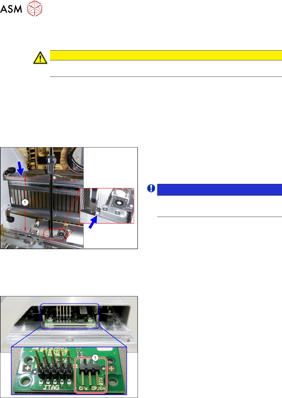
Fig.69: Setting the Height of the Nozzle Station
(taking the standard nozzle station as example)
► The distance(1) between the contact surface of
the nozzle station and the top edge of the upper
guide rail of the gantry needs to be
266.0+0.1/-0.3mm.
You may need to use shim plates to adjust this.
NOTICE!
Alternatively, you can measure from the top
edge of the lower guide rail of the gantry. In this
case the distance is 105.0+0.1/-0.3mm.
.
4.1.2.3 Jumpers on the Nozzle Changer
Overview
Fig.70: Jumpers on the Nozzle Changer
1. Jumper X10
The jumper X10 needs to be set at the following
nozzle changers:
●
Nozzle changer basic structure CPx/all assembly
- short [03103649-xx]
●
Nozzle changer basic structure CPx/all assembly
- long [03103514-xx]