00198628-01_Option_Stationäre-Kamera_TX12_V2_de_en.pdf - 第81页
3 Installation 3.1 Preparatory Steps Assembly Instructions / Montageanleitung SIPLACE TX-Series V2 Stationary Camera Type 25/33 Stationäre Kamera Typ 25/33 10/2018 81 3 Installation CAUTION Do not hold or carry the camer…

2 Brief description
2.8 Required Working Time
80 Assembly Instructions / Montageanleitung SIPLACE TX-Series V2 Stationary Camera Type 25/33 Stationäre Kamera
Typ 25/33 10/2018
3 Installation
3.1 Preparatory Steps
Assembly Instructions / Montageanleitung SIPLACE TX-Series V2 Stationary Camera Type 25/33 Stationäre Kamera
Typ 25/33 10/2018
81
3 Installation
CAUTION
Do not hold or carry the camera by its electronics unit.
The camera electronics assembly is a sensitive unit and can be easily damaged.
► Only hold or carry the camera by its metal frame.
► Always pull the illumination unit carefully up and off.
► The metal housing must always be hooked out of the lower section of the camera.
CAUTION
Crash danger
When fitting the camera, make sure that you observe the correct installation height,
otherwise this could create a risk of head crash.
3.1 Preparatory Steps
► At location 1, move the component trolley out of the machine.
► Switch off the machine, disconnect it from the power supply and secure it to prevent
unauthorized reactivation.
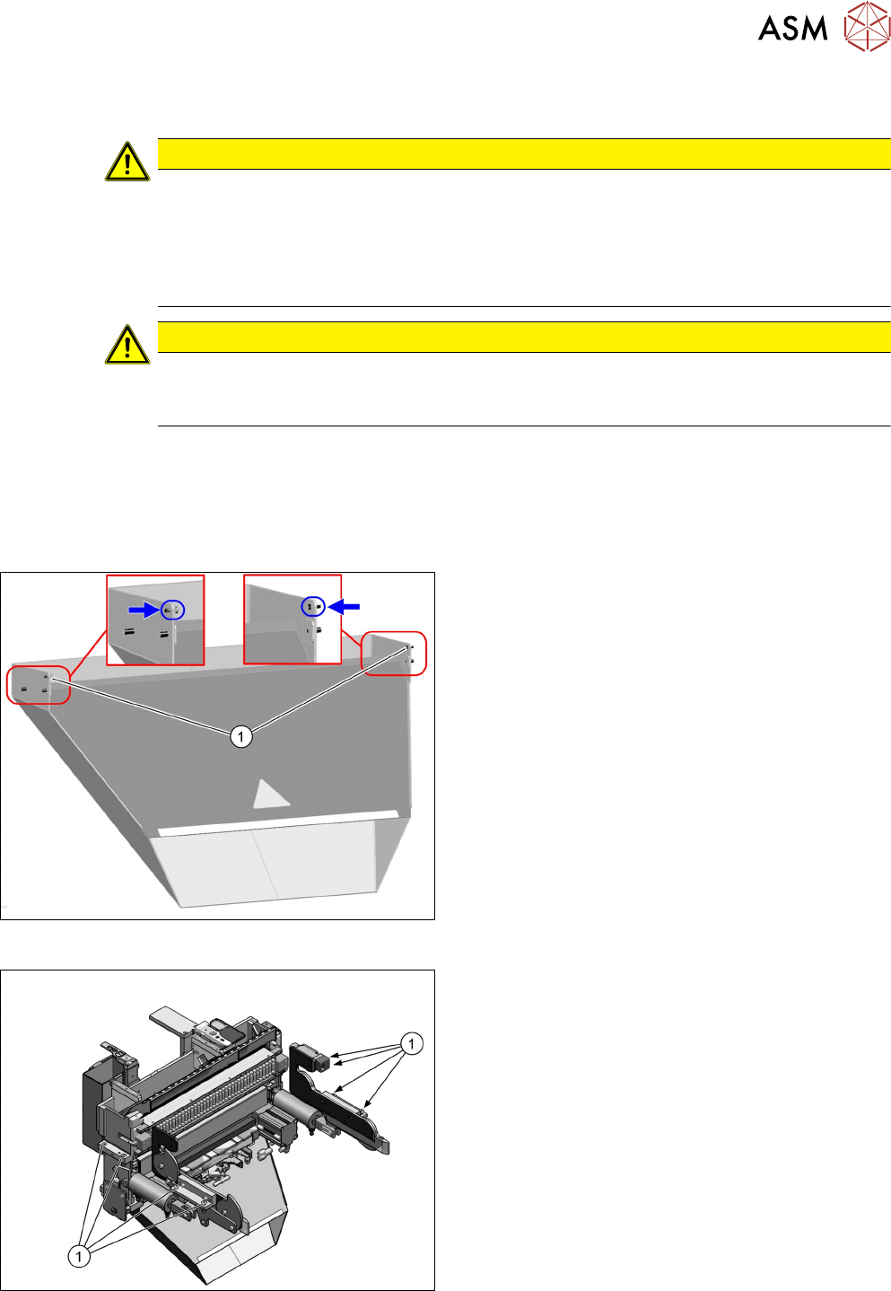
Fig.18: Waste tape chute
► Loosen the two safety screws(1) on the waste
tape chute and unhook it.
Fig.19: COT insert
► You may want to mark the position of the COT
insert to be able to install the COT insert at the
same position later on.
► Remove the eight fastening screws(1) of the
COT insert.
► Pull the COT insert out of the machine a bit for a
better access to the installation position.
3 Installation
3.2 Converting the Reject Box
82 Assembly Instructions / Montageanleitung SIPLACE TX-Series V2 Stationary Camera Type 25/33 Stationäre Kamera
Typ 25/33 10/2018
3.2 Converting the Reject Box
NOTICE
Before installing the camera
It is recommended to convert the reject box before installing the camera.
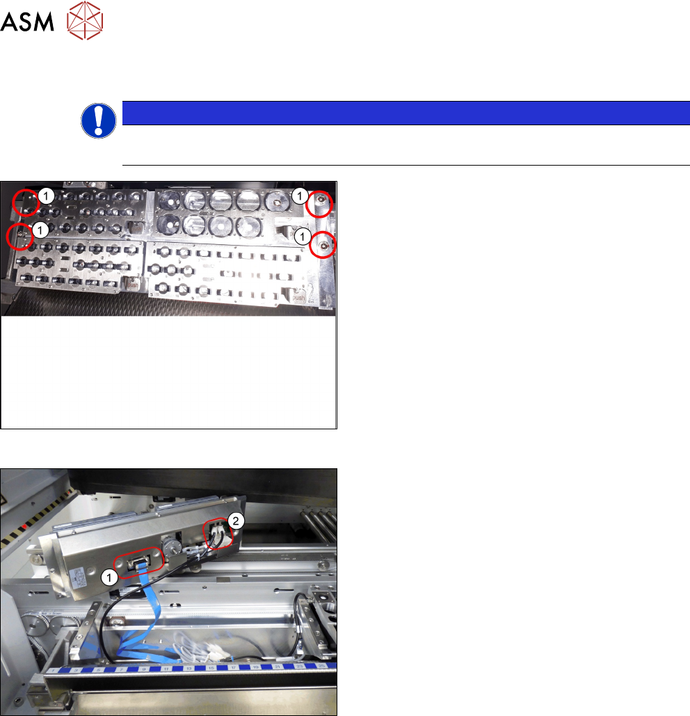
Fig.20: Removing NC 1
► Remove the four screws(1) fastening the nozzle
changer (NC).
Fig.21: Removing NC 2
► Unplug the electrical(1) and pneumatic connec-
tions(2) for the nozzle changer and put the NC
aside.