00198628-01_Option_Stationäre-Kamera_TX12_V2_de_en.pdf - 第92页
3 Installation 3.4 Fitting the Stationary Camera Type SST33 92 Assembly Instructions / Montageanleitung SIPLACE TX-Series V2 Stationary Camera Type 25/33 Stationäre Kamera Typ 25/33 10/2018 Fig.44: Camera spacer plate ►…
3 Installation
3.4 Fitting the Stationary Camera Type SST33
Assembly Instructions / Montageanleitung SIPLACE TX-Series V2 Stationary Camera Type 25/33 Stationäre Kamera
Typ 25/33 10/2018
91
3.4 Fitting the Stationary Camera Type SST33
This section describes the installation of a stationary camera of type SST33 GigE.
For installing a stationary camera of type SST25 GigE, refer to section 3.3 "Fitting the Stationary
Camera Type SST25" [}87].
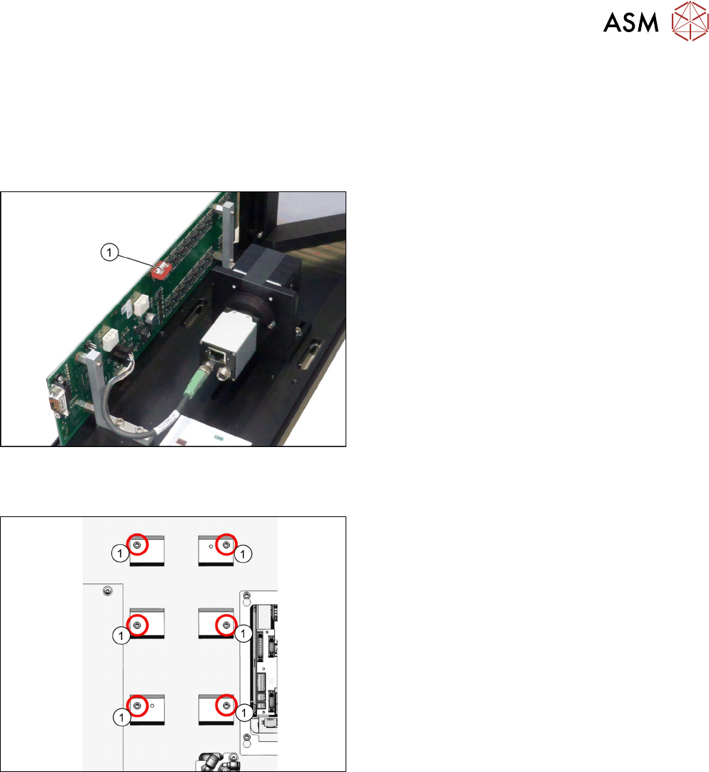
Setting the DIP switches
Fig.42: Setting the DIP switches
► Set the DIP switches(1):
S1.1 to S1.5: OFF
S1.6: ON
(See also 4.2.1.2 "Vision LED Controller VLC33
GigE DTC [03117981-xx]" [}107]).
Fitting the basic camera unit
Fig.43: Screw attachment points for the camera spacer plate
1. Six screw attachment points for the camera
spacer plate
3 Installation
3.4 Fitting the Stationary Camera Type SST33
92 Assembly Instructions / Montageanleitung SIPLACE TX-Series V2 Stationary Camera Type 25/33 Stationäre Kamera
Typ 25/33 10/2018
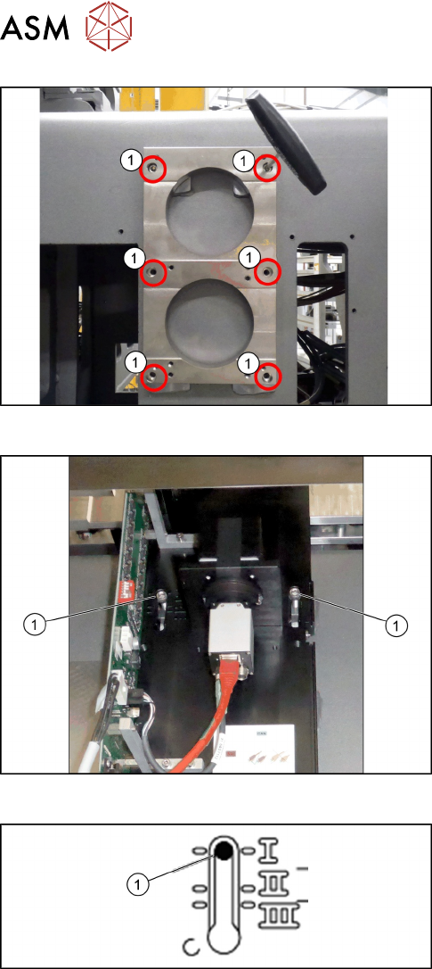
Fig.44: Camera spacer plate
► Screw on the camera distance plate [03136559-
xx] using the six screws [03042574-xx].
Fig.45: Hooking in the basic camera unit
► Place the basic camera unit at its installation
position from above.
► Hook the basic camera unit on the two screws (1)
using the upper keyholes.
Fig.46: Checking the installation height
► Check the installation height of the camera. The
camera must be fitted to the lowest positionI(1).
3 Installation
3.4 Fitting the Stationary Camera Type SST33
Assembly Instructions / Montageanleitung SIPLACE TX-Series V2 Stationary Camera Type 25/33 Stationäre Kamera
Typ 25/33 10/2018
93
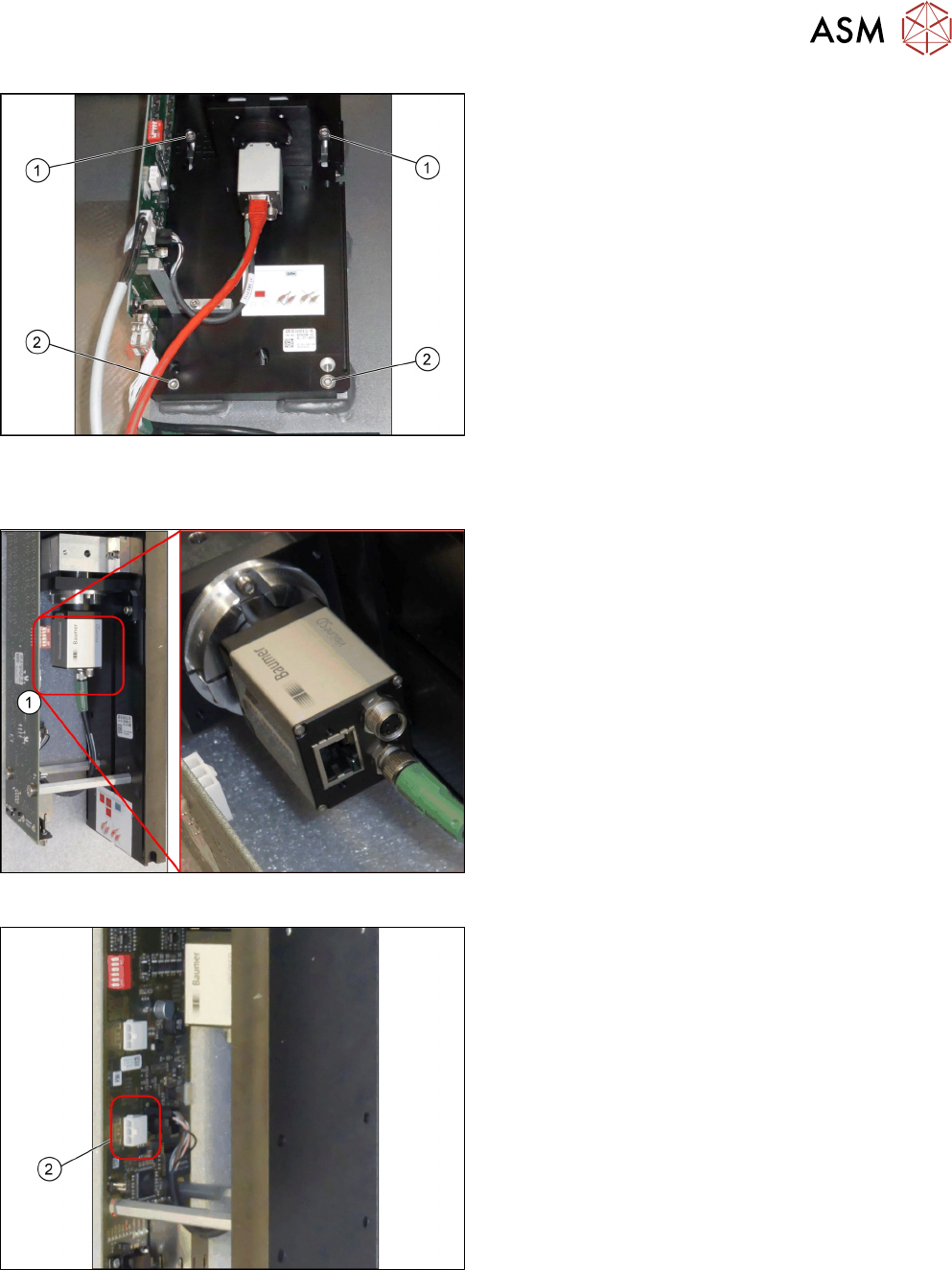
Fig.47: Fixing the camera
► Screw two more screws(2) ISO4762-M6x25-
A2-70 [03042575‑xx] into the lower keyholes.
► Screw all four screws(1) and(2) tight.
Establishing electrical connections
Fig.48: Connection for GigE cable
1. Connection for GigE cable (1)
Fig.49: Connection for power cable cable
1. Connection for power cable cable (2)