00198628-01_Option_Stationäre-Kamera_TX12_V2_de_en.pdf - 第97页
3 Installation 3.6 Making the Settings in the Software Assembly Instructions / Montageanleitung SIPLACE TX-Series V2 Stationary Camera Type 25/33 Stationäre Kamera Typ 25/33 10/2018 97 3.6 Making the Settings in the Soft…
3 Installation
3.5 Completing the Mechanical Work
96 Assembly Instructions / Montageanleitung SIPLACE TX-Series V2 Stationary Camera Type 25/33 Stationäre Kamera
Typ 25/33 10/2018
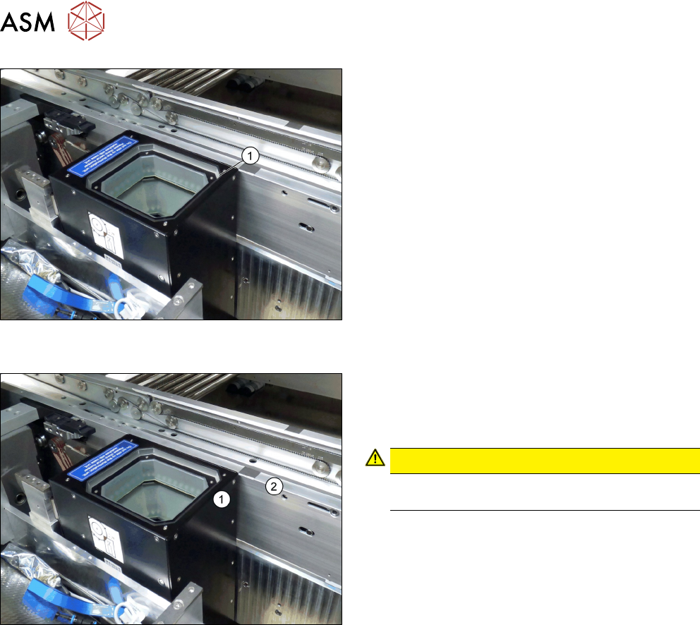
Fig.55: Positioning the upper part and checking the installation
height (SST33 taken as example)
► Put the upper part(1) on the basic unit.
► Check the installation height. The support plate
and the upper part must be below the top edge of
the conveyor rail.
Fig.56: Checking the installation height
► Check the installation height.
When installed correctly, the upper part(1) is
3,5 ±0,1mm higher than the top edge of the
conveyor side (2).
CAUTION!
If the upper part protrudes too far, there is the
danger of a head crash.
.
See also
2 4.2.1.1 "Vision LED Controller VLC25 GigE DTC [03117587-xx]" [}106]
3.5 Completing the Mechanical Work
► Fasten the COT insert to its original position.
► Check and correct the height of the NC holder (see 4.1.2.1 "Setting the Nozzle Changer
Height" [}103]).
► Check and correct the height of the nozzle changer (see 4.1.2.2 "Setting the Nozzle Station
Height" [}104]).
► Check the setting of the jumper on the NC (if one is present).
It must be set to 2-3 (see also 4.1.2.3 "Jumpers on the Nozzle Changer" [}104]).
► Fit the NC and the nozzle station.
► Install the used tape chute in location 1.
► Move the component trolley into the machine.
► Switch the machine on.
► Check the function of the reject bin sensor and set the sensor, if required.
► Make the settings in the software (see 3.6 "Making the Settings in the Software" [}97]).
3 Installation
3.6 Making the Settings in the Software
Assembly Instructions / Montageanleitung SIPLACE TX-Series V2 Stationary Camera Type 25/33 Stationäre Kamera
Typ 25/33 10/2018
97
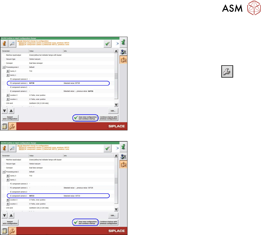
3.6 Making the Settings in the Software
Fig.57: SST25: Saving the configuration
Fig.58: SST33: Saving the configuration
After start-up, the station software notifies you of the
changed hardware. Confirm the change as follows:
► Switch over to the operator level Machine ser-
vice.
►
Switch over to the service menu .
► Go to the Machine Configuration view.
► Check the setting of the PCB camera.
► Confirm the changes with Save new configura-
tion and continue startup.
► Calibrate the camera (see Calibrating the Heads
and Cameras (SW70x)).
The installation is now complete.

3 Installation
3.6 Making the Settings in the Software
98 Assembly Instructions / Montageanleitung SIPLACE TX-Series V2 Stationary Camera Type 25/33 Stationäre Kamera
Typ 25/33 10/2018