00198628-01_Option_Stationäre-Kamera_TX12_V2_de_en.pdf - 第109页
4 Appendix 4.3 Circuit Diagrams Assembly Instructions / Montageanleitung SIPLACE TX-Series V2 Stationary Camera Type 25/33 Stationäre Kamera Typ 25/33 10/2018 109 4.3 Circuit Diagrams
4 Appendix
4.2 Description of Boards
108 Assembly Instructions / Montageanleitung SIPLACE TX-Series V2 Stationary Camera Type 25/33 Stationäre Kamera
Typ 25/33 10/2018
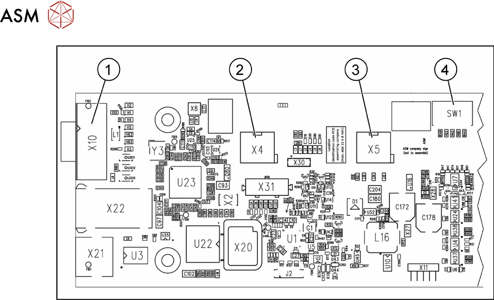
Fig.72: 03117981-01
1 CAN bus 2 X4: Cable for power supply
3 X5: Cable for power supply, bridge to
FC camera
4 DIP switch

4 Appendix
4.3 Circuit Diagrams
Assembly Instructions / Montageanleitung SIPLACE TX-Series V2 Stationary Camera Type 25/33 Stationäre Kamera
Typ 25/33 10/2018
109
4.3 Circuit Diagrams
4 Appendix
4.3 Circuit Diagrams
110 Assembly Instructions / Montageanleitung SIPLACE TX-Series V2 Stationary Camera Type 25/33 Stationäre Kamera
Typ 25/33 10/2018
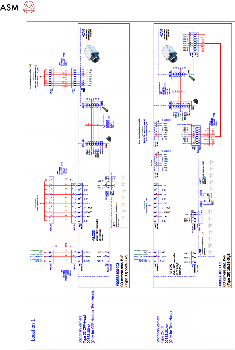
Fig.73: Stationary camera part 1