00198628-01_Option_Stationäre-Kamera_TX12_V2_de_en.pdf - 第65页
1 Introduction 1.1 Safety instructions Assembly Instructions / Montageanleitung SIPLACE TX-Series V2 Stationary Camera Type 25/33 Stationäre Kamera Typ 25/33 10/2018 65 CAUTION Prolonged interruptions to the compressed a…
1 Introduction
1.1 Safety instructions
64 Assembly Instructions / Montageanleitung SIPLACE TX-Series V2 Stationary Camera Type 25/33 Stationäre Kamera
Typ 25/33 10/2018
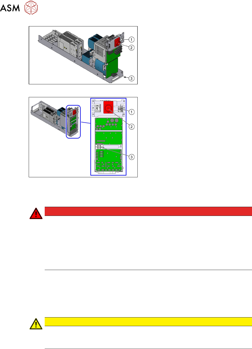
Fig.3: Power supply unit (SIPLACE TX-Series, SMPS)
1. Service socket
2. Main Switch
3. Main power supply cable connection
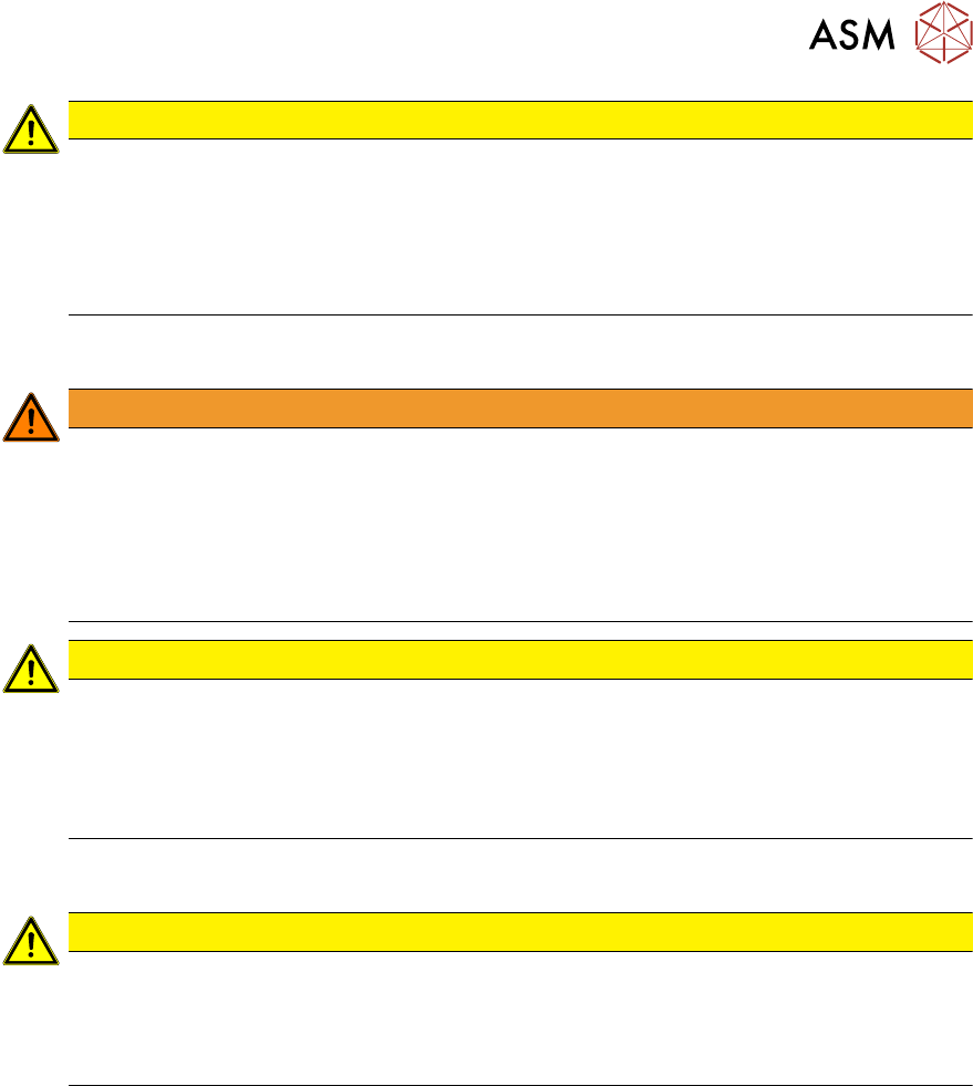
Fig.4: Power supply unit (SIPLACE TX -Series V2,
SMPS)
1. Testing terminals for mains voltage
2. Main switch
3. Testing points for freedom from voltage
(160VDC/300VDC)
The connection for the power supply cable is
located in sector1.
Machine switched off at the main power switch and disconnected
DANGER
Hazardous voltages in the power supply unit!
The power supply unit houses components (capacitors) that can carry hazardous voltages
for about five minutes after the machine has been switched off and the power plug has
been unplugged.
► Wait at least five minutes before your start working on the power supply unit.
► Work on the power supply and the contactor safety breaker (CSB) must only be car-
ried out by service engineers of ASM Assembly Systems GmbH & Co. KG or by
machine owner service engineers who have been trained by ASM.
Compressed air conditions in the machine after switching off at the main switch
When the machine is switched off at the main power switch or if the power supply fails, the electric-
ally-controlled main valve of the compressed air unit closes. The pressure will drop to 0 MPa
(0bar) within five seconds.
1.1.4 Safety instructions for the compressed air supply
CAUTION
Risk of injury from compressed air!
Risk of injury when disconnecting the compressed air lines.
► Never disconnect compressed air lines while they are still pressurized.
1 Introduction
1.1 Safety instructions
Assembly Instructions / Montageanleitung SIPLACE TX-Series V2 Stationary Camera Type 25/33 Stationäre Kamera
Typ 25/33 10/2018
65
CAUTION
Prolonged interruptions to the compressed air supply can cause damage.
When the machine is switched on, do not use the shutoff valve to interrupt the compressed
air supply for more than 30 minutes.
► If you need to shut off the compressed air system for longer in order to carry out your
work, you must switch the machine off at the main switch and disconnect it from the
power supply.
1.1.5 Safety instructions for work on the cutting device
WARNING
Risk of injury when working near the tape cutter.
When working in the area of the tape cutter, move the component trolley out of the machine
and disconnect the machine from the mains supply and the compressed air supply.
► Wait until the operating pressure has dropped to 0 MPa.
► Always secure the machine against unauthorized reactivation.
► Do not reach into the tape cutter.
CAUTION
Risk of injury when performing service work on the tape cutter.
Never support the tape cutter on your body, e.g., on your knees or thighs. Do not place
your feet under the tape cutter.
► Wear appropriately thick protective gloves.
► When removing/fitting the tape cutter, hold it only outside on the left and right.
1.1.6 Safety instructions for the gantry
CAUTION
Moving the gantry can damage the placement head.
When moving the gantry, observe the following:
► NEVER move the gantry by pushing with your hands against the placement head.
► NEVER push the gantry while the Z axis is lowered.
1 Introduction
1.1 Safety instructions
66 Assembly Instructions / Montageanleitung SIPLACE TX-Series V2 Stationary Camera Type 25/33 Stationäre Kamera
Typ 25/33 10/2018
1.1.7 Classification of the optical systems
1.1.7.1 Classification of the whole machine
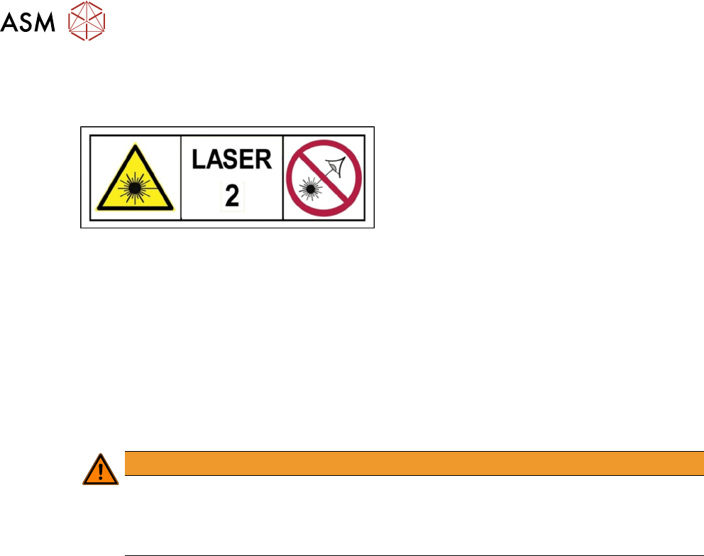
Fig.5: Laser class 2
The ready-to-operate overall machine is assigned
to laser class°2.
The laser classes are determined according to
DIN EN 60825-1:2014.
1.1.7.2 Laser classification
The following modules are assigned to laser class 2:
●
ICR850 series PCB barcode scanner
●
Component sensor on the SpeedStar
●
Component sensor on the MultiStar
●
Laser light barriers at the board conveyor
1.1.7.3 Classification of the camera systems
WARNING
LEDs
The camera illumination systems are fitted with light LEDs. These are assigned to risk
group 1 according to IEC 62741:2006.
► Do not look into beam!