00198628-01_Option_Stationäre-Kamera_TX12_V2_de_en.pdf - 第94页
3 Installation 3.4 Fitting the Stationary Camera Type SST33 94 Assembly Instructions / Montageanleitung SIPLACE TX-Series V2 Stationary Camera Type 25/33 Stationäre Kamera Typ 25/33 10/2018 Fig.50: Connection for CAN bu…
3 Installation
3.4 Fitting the Stationary Camera Type SST33
Assembly Instructions / Montageanleitung SIPLACE TX-Series V2 Stationary Camera Type 25/33 Stationäre Kamera
Typ 25/33 10/2018
93
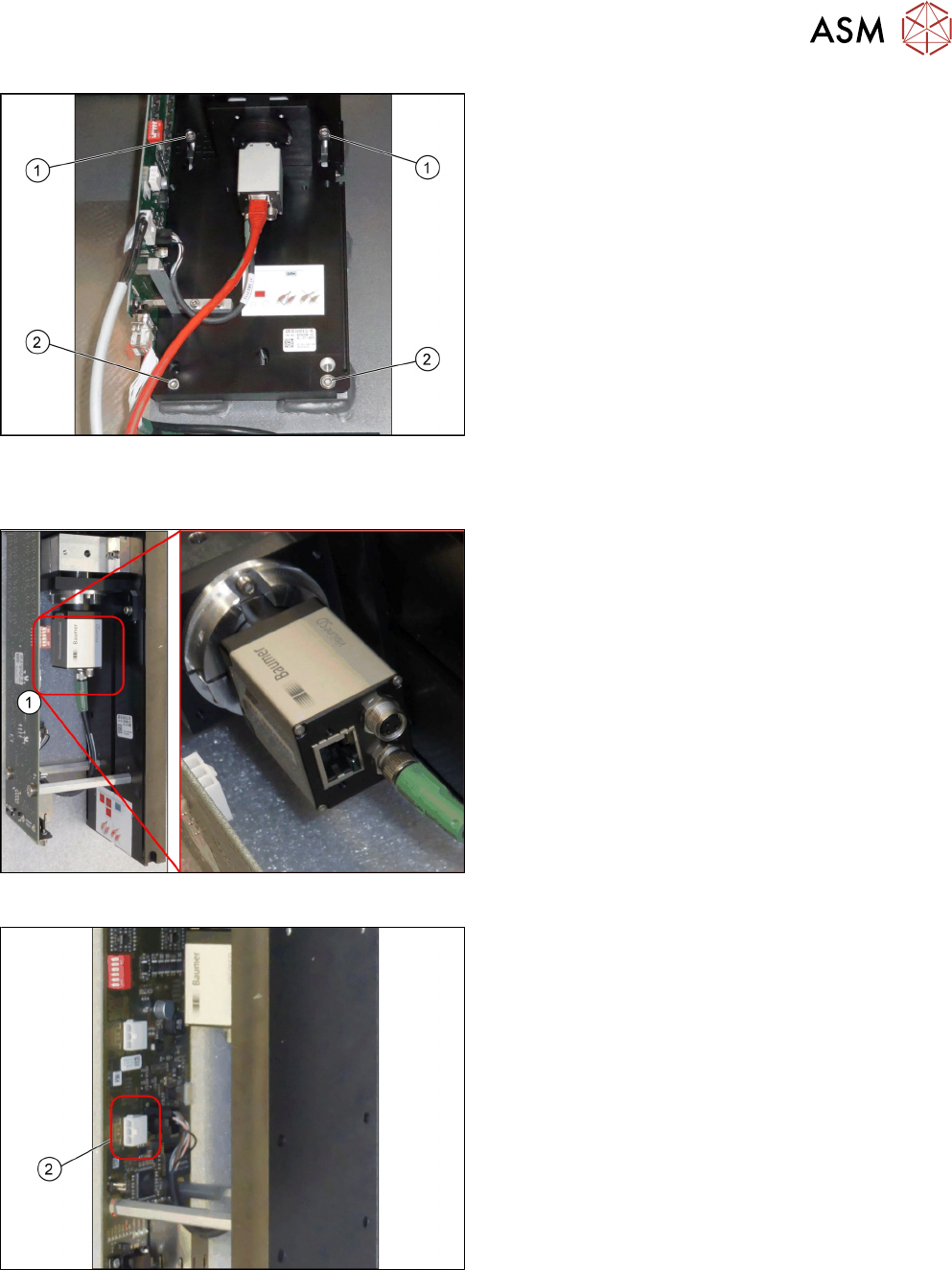
Fig.47: Fixing the camera
► Screw two more screws(2) ISO4762-M6x25-
A2-70 [03042575‑xx] into the lower keyholes.
► Screw all four screws(1) and(2) tight.
Establishing electrical connections
Fig.48: Connection for GigE cable
1. Connection for GigE cable (1)
Fig.49: Connection for power cable cable
1. Connection for power cable cable (2)
3 Installation
3.4 Fitting the Stationary Camera Type SST33
94 Assembly Instructions / Montageanleitung SIPLACE TX-Series V2 Stationary Camera Type 25/33 Stationäre Kamera
Typ 25/33 10/2018
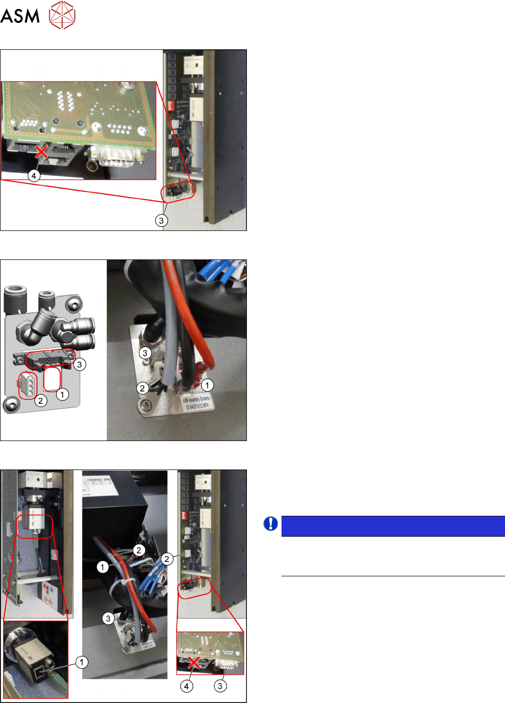
Fig.50: Connection for CAN bus cable
Connection for CAN bus cable (3)
Multiplexer (not in use) (4).
Fig.51: Connections on the machine
1. GigE cable W3: Extension camera bus stat.
camera [03148099-xx]
2. Power cable: Extension power stat. camera
W1[03148097-xx]
3. CAN bus cable W2: Extension CAN bus stat.
camera [03148098-xx]
Fig.52: Establishing electrical connections
► Run the cables (1), (2) and (3) from the camera
to the pneumatics feedthrough.
► Connect the cables.
NOTICE!
Make sure to connect the GigE cable correctly.
The multiplexer connection at the lower end of
the board is not used.
.
3 Installation
3.4 Fitting the Stationary Camera Type SST33
Assembly Instructions / Montageanleitung SIPLACE TX-Series V2 Stationary Camera Type 25/33 Stationäre Kamera
Typ 25/33 10/2018
95
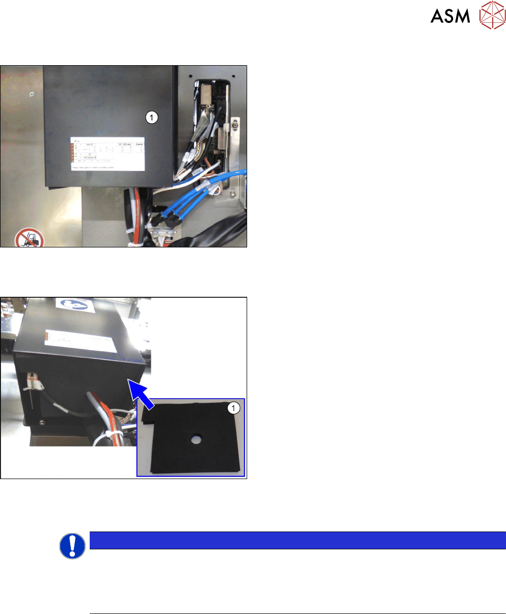
Hooking in the bottom cover
Fig.53: Hooking in the bottom cover (SST33 taken as example)
► Hook in the bottom cover(1) of the camera.
Inserting the dust cover
Fig.54: Inserting the dust cover (SST33 as example)
► Insert the dust cover made of foam plastic(1) into
the bottom cover.
Positioning the upper part and checking the installation height
NOTICE
The camera upper section has a fixed assignment to the camera lower section.
The camera upper section may not be used with another camera lower section. Both the
upper and lower sections are mechanically and electrically coordinated and may not be ex-
changed for use with other cameras. The serial and version numbers of the top and bottom
sections of the camera must be identical.