00198628-01_Option_Stationäre-Kamera_TX12_V2_de_en.pdf - 第86页
3 Installation 3.2 Converting the Reject Box 86 Assembly Instructions / Montageanleitung SIPLACE TX-Series V2 Stationary Camera Type 25/33 Stationäre Kamera Typ 25/33 10/2018 Fig.31: Fitting the NC holder ► Fit the righ…
3 Installation
3.2 Converting the Reject Box
Assembly Instructions / Montageanleitung SIPLACE TX-Series V2 Stationary Camera Type 25/33 Stationäre Kamera
Typ 25/33 10/2018
85
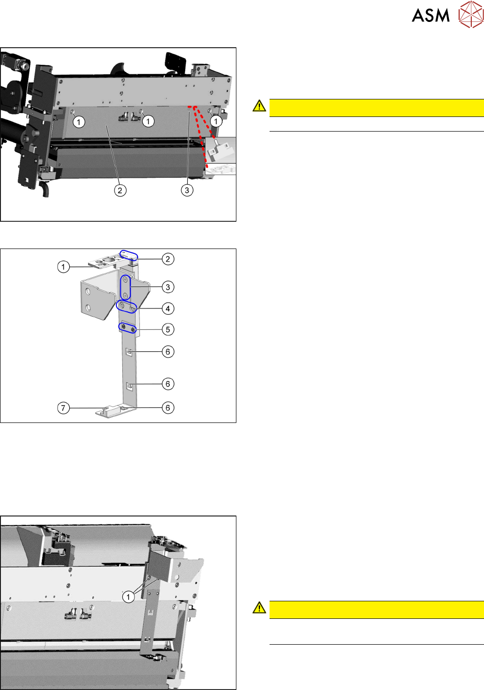
Fig.28: Fitting the rear cover
► Fasten the rear cover(2) with three screws(1).
The sensor cable and the adapter assembly
nozzle station TX V2 are run through the
opening(3) in the cover.
CAUTION!
Make sure not clamp any hoses or cables.
.
Fig.29: Fitting the reject bin holder
1. Nozzle station [03106821‑xx]
The nozzle station is fitted after measuring the
height.
2. Fastening screws of the nozzle station
[00333782‑xx]
3. Fastening screws for retaining bracket
ISO10642-M5x10-A2-70 [03082832‑xx]
4. Fastening screws of the complete holder on the
COT insert DIN7984-M6x12-A2-70
[03081847‑xx]
5. Fastening screws ISO 7380-2 M 3 x 6-A2-70
[03099571-xx], only for setting the sensor height
6. Three lugs for cable ties
7. Sensor [03088550‑xx]
The sensor that is already installed and cabled
on the insert is used.
► Fit the individual parts of the reject bin holder.
► Use the cable ties to fix the sensor to the three
lugs.
Fig.30: Fitting the reject bin holder
► Fit the reject bin holder with two fastening screws
DIN7984-M6x12-A2-70 [03081847-xx](1) on the
COT insert.
Push the sensor cable and the adapter assembly
nozzle station TX V2 behind the cover as far as
possible and connect the pneumatic hose to the
nozzle station.
CAUTION!
If too much cable length lies in front of the cover,
the reject bin may damage the cable.
.
3 Installation
3.2 Converting the Reject Box
86 Assembly Instructions / Montageanleitung SIPLACE TX-Series V2 Stationary Camera Type 25/33 Stationäre Kamera
Typ 25/33 10/2018
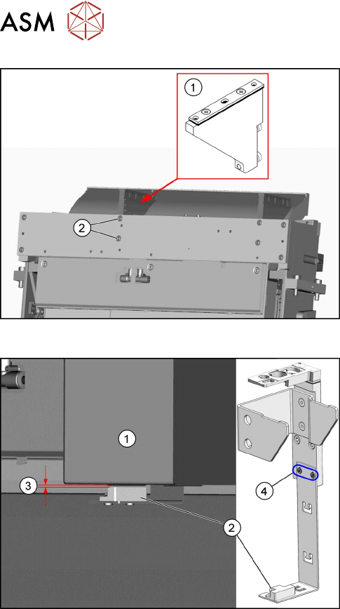
Fig.31: Fitting the NC holder
► Fit the right NC holder(1) with two fastening
screws DIN 7984-M6 x 12-A2-70 [03081847-
xx](2). The right NC holder is replaced by the
supplied version without nozzle station.
► Do not fit the NC and the nozzle station yet!
Fig.32: Setting the sensor
1. Reject box
2. Sensor
3. Distance 2.0+/-1.0mm
4. Fastening screws for setting the senor height
► Insert the reject bin.
► Set the sensor to a distance of 2.0+/-1.0mm
from the reject bin.
3 Installation
3.3 Fitting the Stationary Camera Type SST25
Assembly Instructions / Montageanleitung SIPLACE TX-Series V2 Stationary Camera Type 25/33 Stationäre Kamera
Typ 25/33 10/2018
87
3.3 Fitting the Stationary Camera Type SST25
This section describes the installation of a stationary camera of type SST25 GigE.
For installing a stationary camera of type SST33 GigE, refer to section 3.4 "Fitting the Stationary
Camera Type SST33" [}91].
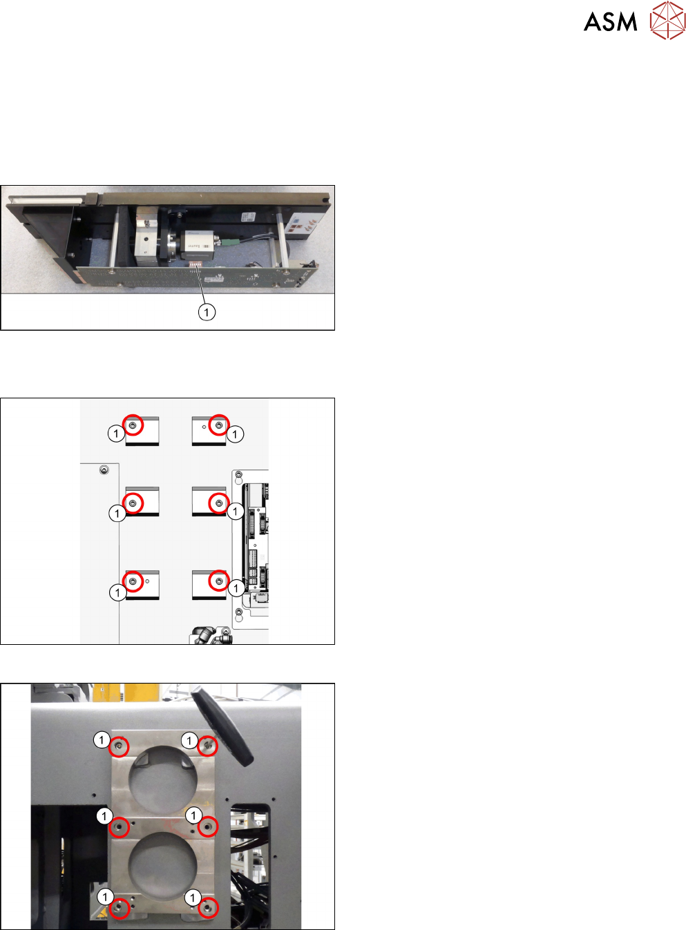
Setting the DIP switches
Fig.33: Setting the DIP switches
► Set the DIP switches(1):
S1.1 to S1.6: OFF
(See also 4.2.1.1 "Vision LED Controller VLC25
GigE DTC [03117587-xx]" [}106]).
Fitting the support plate
Fig.34: Screw attachment points for the camera spacer plate
1. Six screw attachment points for the camera
spacer plate
Fig.35: Camera spacer plate
► Screw the camera spacer plate [03136559-xx] to
the blocks using the six screws [03042574-xx]
(1).