00198628-01_Option_Stationäre-Kamera_TX12_V2_de_en.pdf - 第87页
3 Installation 3.3 Fitting the Stationary Camera Type SST25 Assembly Instructions / Montageanleitung SIPLACE TX-Series V2 Stationary Camera Type 25/33 Stationäre Kamera Typ 25/33 10/2018 87 3.3 Fitting the Stationary Cam…
3 Installation
3.2 Converting the Reject Box
86 Assembly Instructions / Montageanleitung SIPLACE TX-Series V2 Stationary Camera Type 25/33 Stationäre Kamera
Typ 25/33 10/2018
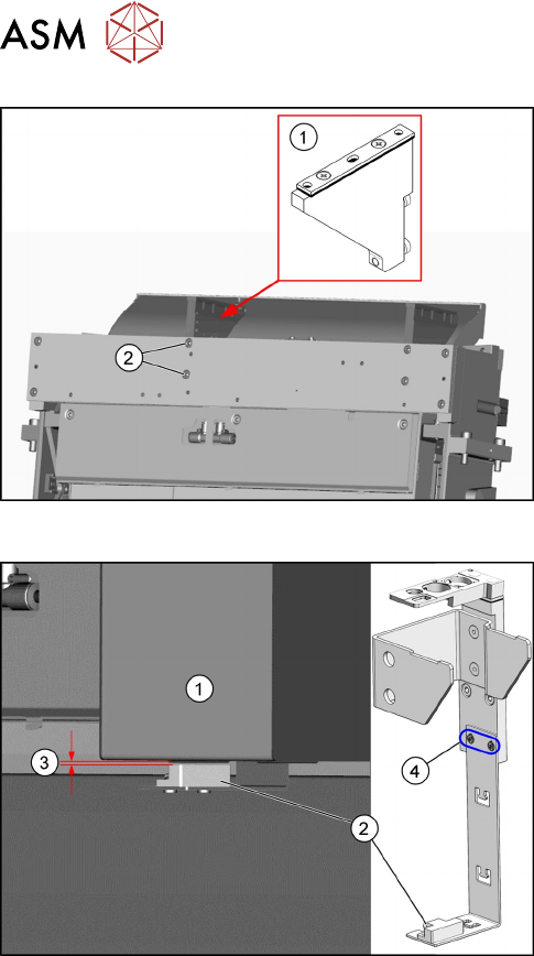
Fig.31: Fitting the NC holder
► Fit the right NC holder(1) with two fastening
screws DIN 7984-M6 x 12-A2-70 [03081847-
xx](2). The right NC holder is replaced by the
supplied version without nozzle station.
► Do not fit the NC and the nozzle station yet!
Fig.32: Setting the sensor
1. Reject box
2. Sensor
3. Distance 2.0+/-1.0mm
4. Fastening screws for setting the senor height
► Insert the reject bin.
► Set the sensor to a distance of 2.0+/-1.0mm
from the reject bin.
3 Installation
3.3 Fitting the Stationary Camera Type SST25
Assembly Instructions / Montageanleitung SIPLACE TX-Series V2 Stationary Camera Type 25/33 Stationäre Kamera
Typ 25/33 10/2018
87
3.3 Fitting the Stationary Camera Type SST25
This section describes the installation of a stationary camera of type SST25 GigE.
For installing a stationary camera of type SST33 GigE, refer to section 3.4 "Fitting the Stationary
Camera Type SST33" [}91].
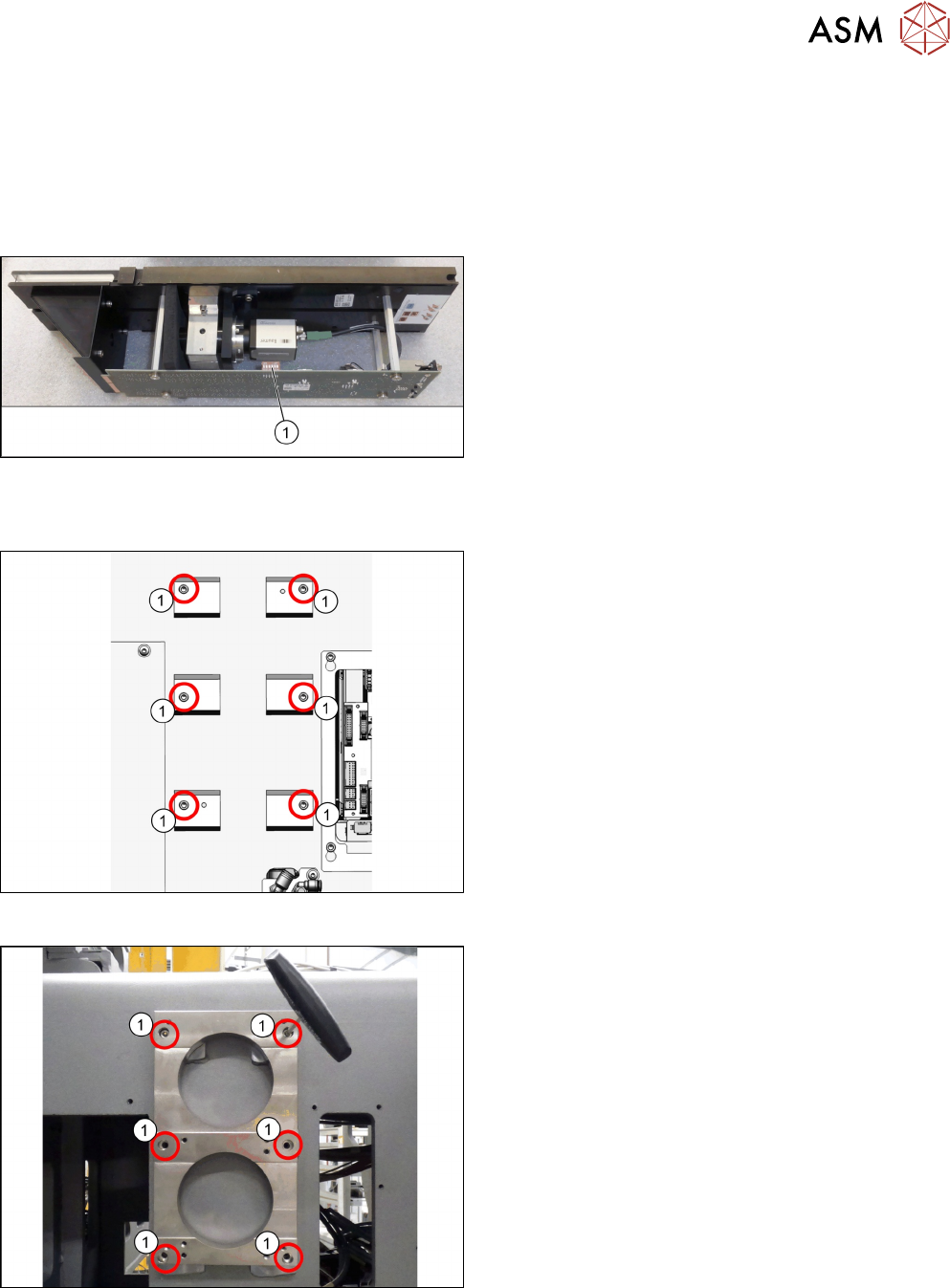
Setting the DIP switches
Fig.33: Setting the DIP switches
► Set the DIP switches(1):
S1.1 to S1.6: OFF
(See also 4.2.1.1 "Vision LED Controller VLC25
GigE DTC [03117587-xx]" [}106]).
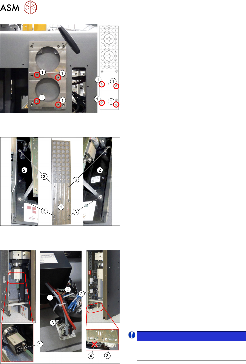
Fitting the support plate
Fig.34: Screw attachment points for the camera spacer plate
1. Six screw attachment points for the camera
spacer plate
Fig.35: Camera spacer plate
► Screw the camera spacer plate [03136559-xx] to
the blocks using the six screws [03042574-xx]
(1).
3 Installation
3.3 Fitting the Stationary Camera Type SST25
88 Assembly Instructions / Montageanleitung SIPLACE TX-Series V2 Stationary Camera Type 25/33 Stationäre Kamera
Typ 25/33 10/2018
Fig.36: Fitting the support plate
1. Four fastening screws of the support plate
DIN912-M6x12-A2-70[03045087‑xx]
2. Support plate FC [03077911‑xx]
► Fasten the support plate [03077911‑xx] at the
camera spacer plate using the four screws (1).
Fitting the basic camera unit
Fig.37: Fitting the basic camera unit
1. Support plate
2. Basic camera unit
3. Four fastening screws of the basic camera unit
ISO4762-M6x20-A2-70 [03042574‑xx]
► Place the basic camera unit at its installation
position from above.
► Fasten the basic camera unit to the support plate
with four screws.
Establishing electrical connections
Fig.38: Establishing electrical connections
1. a) GigE cable W3: Extension camera bus stat.
camera [03148099-xx]
b) Connection for GigE cable
2. a) Power cable: Extension power stat. camera
W1[03148097-xx]
b) Connection for power cable
3. a) CAN bus cable W2: Extension CAN bus stat.
camera [03148098-xx]
b) Connection for CAN bus cable
4. Multiplexer (not in use)
► Connect the cables.
NOTICE!
Make sure to connect the GigE cable correctly.
The multiplexer connection at the lower end of
the board is not used.
.