00198628-01_Option_Stationäre-Kamera_TX12_V2_de_en.pdf - 第91页
3 Installation 3.4 Fitting the Stationary Camera Type SST33 Assembly Instructions / Montageanleitung SIPLACE TX-Series V2 Stationary Camera Type 25/33 Stationäre Kamera Typ 25/33 10/2018 91 3.4 Fitting the Stationary Cam…
3 Installation
3.3 Fitting the Stationary Camera Type SST25
90 Assembly Instructions / Montageanleitung SIPLACE TX-Series V2 Stationary Camera Type 25/33 Stationäre Kamera
Typ 25/33 10/2018
Positioning the upper part and checking the installation height
NOTICE
The camera upper section has a fixed assignment to the camera lower section.
The camera upper section may not be used with another camera lower section. Both the
upper and lower sections are mechanically and electrically coordinated and may not be ex-
changed for use with other cameras. The serial and version numbers of the top and bottom
sections of the camera must be identical.
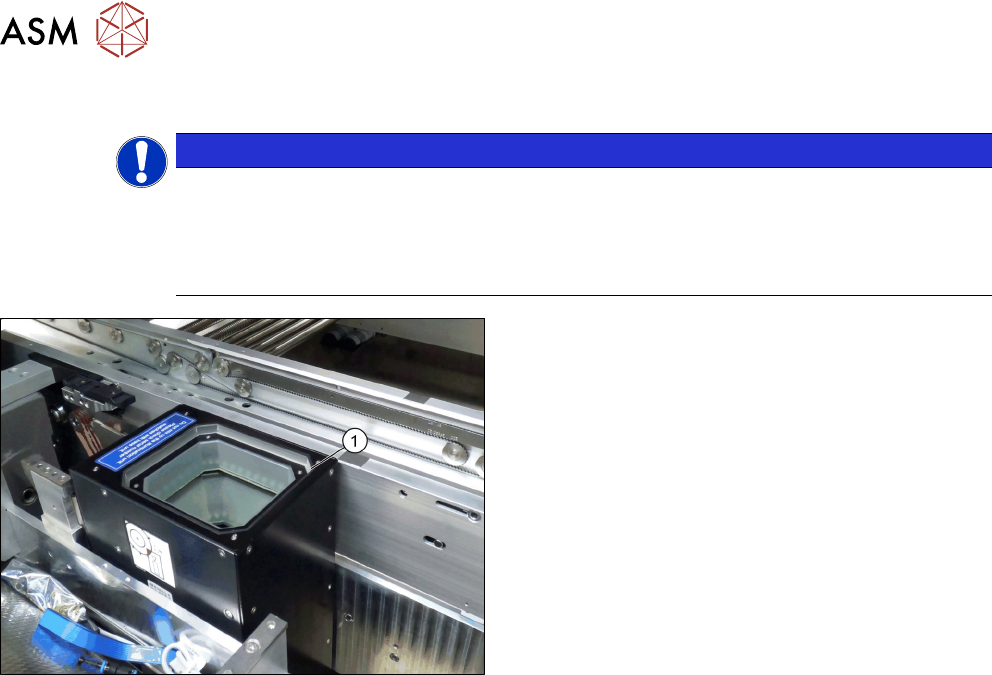
Fig.41: Positioning the upper part and checking the installation
height (SST33 taken as example)
► Put the upper part(1) on the basic unit.
► Check the installation height. The support plate
and the upper part must be below the top edge of
the conveyor rail.
3 Installation
3.4 Fitting the Stationary Camera Type SST33
Assembly Instructions / Montageanleitung SIPLACE TX-Series V2 Stationary Camera Type 25/33 Stationäre Kamera
Typ 25/33 10/2018
91
3.4 Fitting the Stationary Camera Type SST33
This section describes the installation of a stationary camera of type SST33 GigE.
For installing a stationary camera of type SST25 GigE, refer to section 3.3 "Fitting the Stationary
Camera Type SST25" [}87].
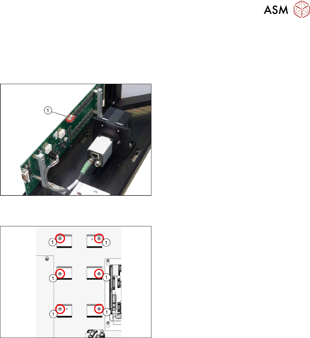
Setting the DIP switches
Fig.42: Setting the DIP switches
► Set the DIP switches(1):
S1.1 to S1.5: OFF
S1.6: ON
(See also 4.2.1.2 "Vision LED Controller VLC33
GigE DTC [03117981-xx]" [}107]).
Fitting the basic camera unit
Fig.43: Screw attachment points for the camera spacer plate
1. Six screw attachment points for the camera
spacer plate
3 Installation
3.4 Fitting the Stationary Camera Type SST33
92 Assembly Instructions / Montageanleitung SIPLACE TX-Series V2 Stationary Camera Type 25/33 Stationäre Kamera
Typ 25/33 10/2018
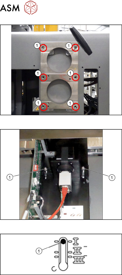
Fig.44: Camera spacer plate
► Screw on the camera distance plate [03136559-
xx] using the six screws [03042574-xx].
Fig.45: Hooking in the basic camera unit
► Place the basic camera unit at its installation
position from above.
► Hook the basic camera unit on the two screws (1)
using the upper keyholes.
Fig.46: Checking the installation height
► Check the installation height of the camera. The
camera must be fitted to the lowest positionI(1).