00198628-01_Option_Stationäre-Kamera_TX12_V2_de_en.pdf - 第105页
4 Appendix 4.1 Excerpts from the Service Manual Assembly Instructions / Montageanleitung SIPLACE TX-Series V2 Stationary Camera Type 25/33 Stationäre Kamera Typ 25/33 10/2018 105 Preparation NOTICE Before installation Du…
4 Appendix
4.1 Excerpts from the Service Manual
104 Assembly Instructions / Montageanleitung SIPLACE TX-Series V2 Stationary Camera Type 25/33 Stationäre Kamera
Typ 25/33 10/2018
► The setting value (3) is 277+/‑0.2mm.
(Deviating values for Mixed Mode option, see above.)
You can adjust the height, where necessary, by removing or adding NC adjusting plates.
CAUTION
Crash hazard!
Do not place too many adjusting plates underneath.
► Calibrate the position of the nozzle changer.
4.1.2.2 Setting the Nozzle Station Height
Parts, Equipment and Tools
●
Measuring scale
●
Adjusting plates: support for nozzle reject device [03039514-xx]
Setting
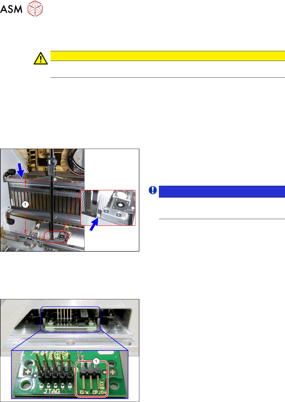
Fig.69: Setting the Height of the Nozzle Station
(taking the standard nozzle station as example)
► The distance(1) between the contact surface of
the nozzle station and the top edge of the upper
guide rail of the gantry needs to be
266.0+0.1/-0.3mm.
You may need to use shim plates to adjust this.
NOTICE!
Alternatively, you can measure from the top
edge of the lower guide rail of the gantry. In this
case the distance is 105.0+0.1/-0.3mm.
.
4.1.2.3 Jumpers on the Nozzle Changer
Overview
Fig.70: Jumpers on the Nozzle Changer
1. Jumper X10
The jumper X10 needs to be set at the following
nozzle changers:
●
Nozzle changer basic structure CPx/all assembly
- short [03103649-xx]
●
Nozzle changer basic structure CPx/all assembly
- long [03103514-xx]
4 Appendix
4.1 Excerpts from the Service Manual
Assembly Instructions / Montageanleitung SIPLACE TX-Series V2 Stationary Camera Type 25/33 Stationäre Kamera
Typ 25/33 10/2018
105
Preparation
NOTICE
Before installation
Due to the design, this setting must be performed before installation in the machine.
► If the new nozzle changer is being fitted as a spare part in a machine with I/O module
control, you will need to reconnect the jumper to pin 1-2.
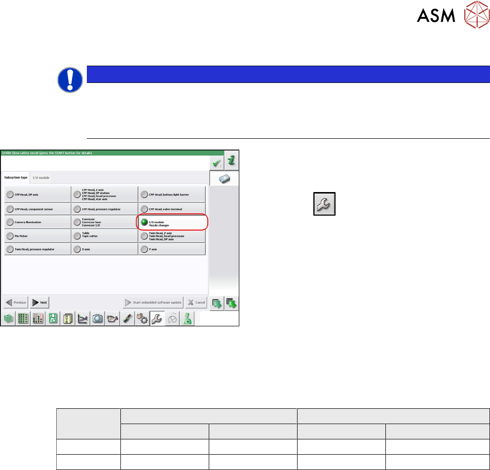
Fig.71: Checking the I/A module control
To check whether the machine has I/O module control,
proceed as follows:
► Switch over to the operator level Service.
► Click the button.
► Click on the Embedded software button.
► Click the Update subsystem button.
► If an I/O module control is present, you will see
the entry Nozzle Changer at I/O Module.
Setting
► Set the correct value on the jumper for your head type, software and control method.
Jumper X10
Head SW <= 706.x SW >= 707.x
I/O controller XFCU I/O controller XFCU
CPx, DLM 1-2 1-2 1-2 2-3
C&P20P --- --- --- 2-3 (factory settings)
4 Appendix
4.2 Description of Boards
106 Assembly Instructions / Montageanleitung SIPLACE TX-Series V2 Stationary Camera Type 25/33 Stationäre Kamera
Typ 25/33 10/2018
4.2 Description of Boards
4.2.1 Stationary cameras
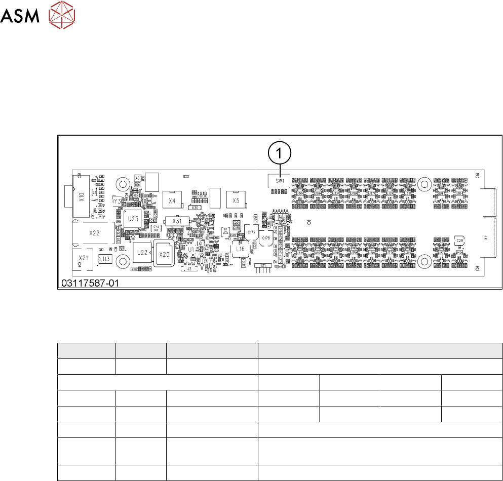
4.2.1.1 Vision LED Controller VLC25 GigE DTC [03117587-xx]
This board is part of the stationary cameras SST25 GigE.
1 DIP switch SW1
DIP switch S1 for SST25 [03117981-01]
Switch Status Signal name Description
S1.1 OFF VCU_CODE OFF: normal operation, ON: Reset
Gantry 1 Gantry 2 Gantry 3 Gantry 4
S1.2 ON/OFF PORTAL_ID_0 OFF ON OFF ON
S1.3 ON/OFF GANTRY_ID_1 OFF OFF ON ON
S1.4 OFF SMD_LED OFF: standard LED, ON: SMD LED
S1.5 OFF CAN_H OFF: with CAN terminator
ON: without CAN terminator
S1.6 OFF CAN_GROUP OFF: FC camera, ON: IC camera