00198628-01_Option_Stationäre-Kamera_TX12_V2_de_en.pdf - 第102页
4 Appendix 4.1 Excerpts from the Service Manual 102 Assembly Instructions / Montageanleitung SIPLACE TX-Series V2 Stationary Camera Type 25/33 Stationäre Kamera Typ 25/33 10/2018 Fig.65: Results view ► Click Results to …
4 Appendix
4.1 Excerpts from the Service Manual
Assembly Instructions / Montageanleitung SIPLACE TX-Series V2 Stationary Camera Type 25/33 Stationäre Kamera
Typ 25/33 10/2018
101
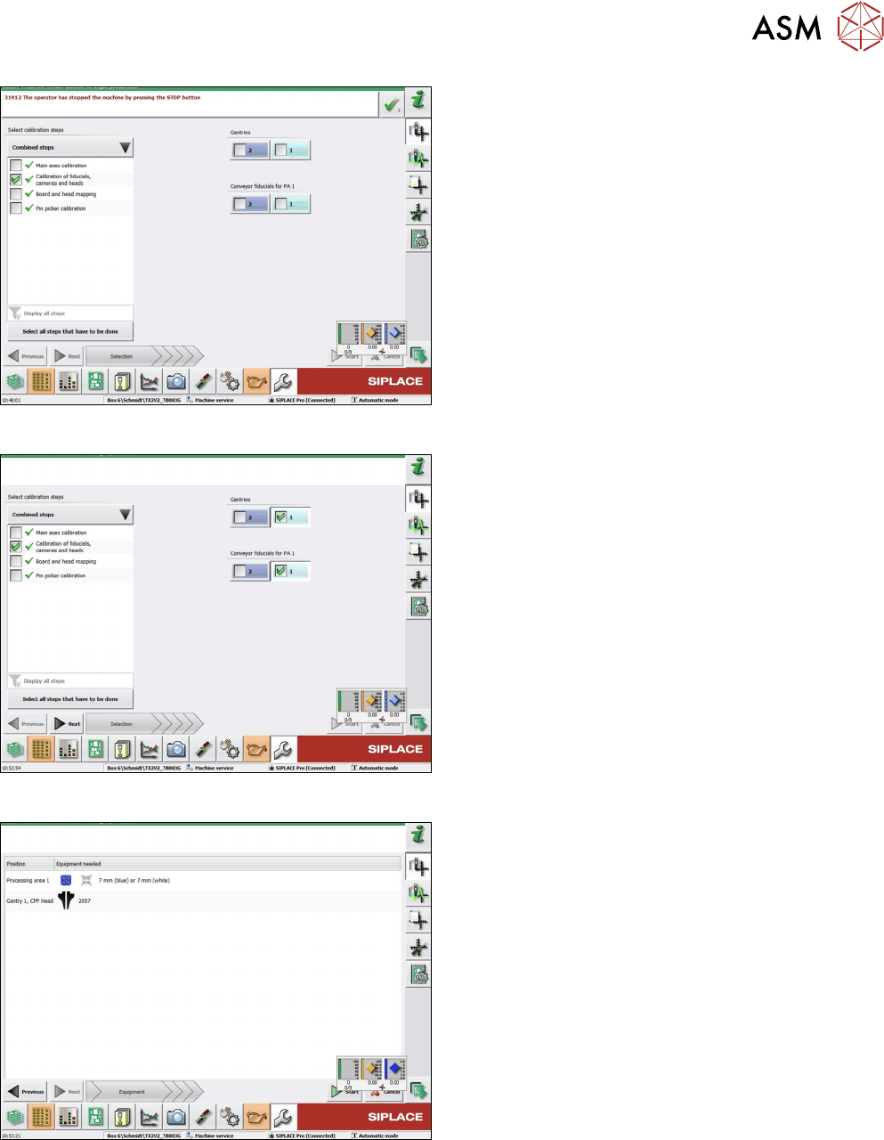
Fig.62: Combined steps view
► On the left-hand side, under Combined steps,
select the check box Calibration of fiducials,
cameras and heads.
► If you selected Display all steps on the left-hand
side, select Calibration of cameras and heads.
► Under Gantries, select the location. For a TX
machine, always location 1.
► Click Next.
Fig.63: Prerequisites view
Prerequisites view.
► Click on Start to start the calibration.
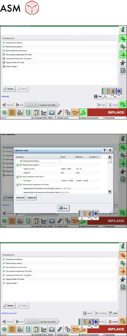
Fig.64: Calibration steps and status view
Calibration steps and status view.
4 Appendix
4.1 Excerpts from the Service Manual
102 Assembly Instructions / Montageanleitung SIPLACE TX-Series V2 Stationary Camera Type 25/33 Stationäre Kamera
Typ 25/33 10/2018
Fig.65: Results view
► Click Results to display detailled information (im-
portant in case of an error).
Fig.66: Save view
► Click Save after successful calibration.
Fig.67: Save button
► Click the Save button.
ð Calibration has finished.
4 Appendix
4.1 Excerpts from the Service Manual
Assembly Instructions / Montageanleitung SIPLACE TX-Series V2 Stationary Camera Type 25/33 Stationäre Kamera
Typ 25/33 10/2018
103
4.1.2 Nozzle Changer Setting
4.1.2.1 Setting the Nozzle Changer Height
Parts, equipment and tools
●
Measuring scale
●
NC shim plate (0.3mm) [03021079-xx]
Overview
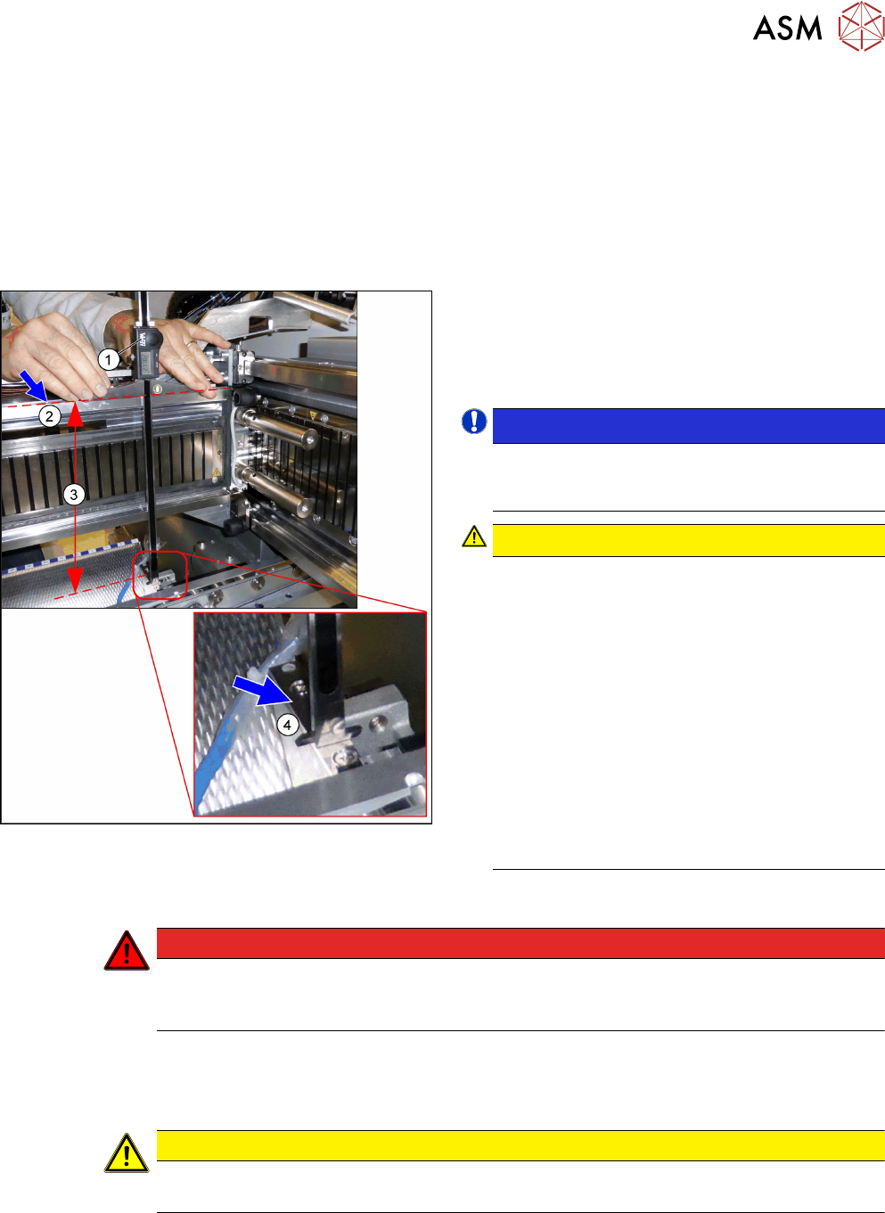
Fig.68: Overview of measurement procedure
1. Measuring scale
2. Top edge of the X axis upper linear guide
3. Values to be set (277 +/- 0.2 mm)
4. Nozzle changer contact surface
NOTICE!
Alternatively, you can measure from the top
edge of the lower guide rail of the gantry. In this
case the distance is 116.0+/‑0.2mm.
.
CAUTION!
Only with mixed mode option
If applicable, observe the deviating measure-
ments for the mixed mode option:
Installation height of NC:
280.65 +/ 0.2 mm
Measured from the upper edge of the top linear
guide
OR
119.65 +/ 0.2 mm
Measured from the upper edge of the bottom lin-
ear guide
See also the assembly instruction manual "Op-
tion Mixed Mode – SIPLACE
TX2i" [00198536‑xx]
.
Adjustment
DANGER
Strong permanent magnet fields
Observe the safety instructions in section 1.1.2 "Safety instructions for working with strong
magnetic fields" [}62].
► Remove the nozzle changer.
► During the following inside measurement make sure that the tip of the measuring scale does
not tough the magnetic strip as this might scratch it!
CAUTION
Strong magnetic forces
Place a suitable plastic plate between the magnet and measuring scale, if required.
► Position the measuring scale(1) on the top edge of the X axis upper linear guide(2) and
measure the distance to the nozzle changer contact surface(4).
► Hold the measuring scale vertically.