YAMAHA-YG系列 换螺杆指导书.pdf - 第10页
Service Engineer Service I nformati on SI080 2008 E-000 = YG series: Replacement proc edure for ball screws of each axis 10/65 Wh en assembling the parts of YG88R and Y G100R models. 1) Move the SLEE VE,BRG to the posi…
Service Engineer
Service Information
SI0802008E-000= YG series: Replacement procedure for ball screws of each axis
9/65
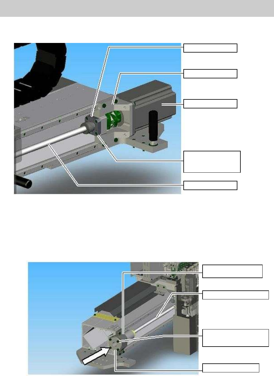
2. Set the SUPPORT UNIT in the HOLDER MOTOR (No.3 in Figure 1) and fix it by fully
tightening the four bolts (M4*14).
Figure 8
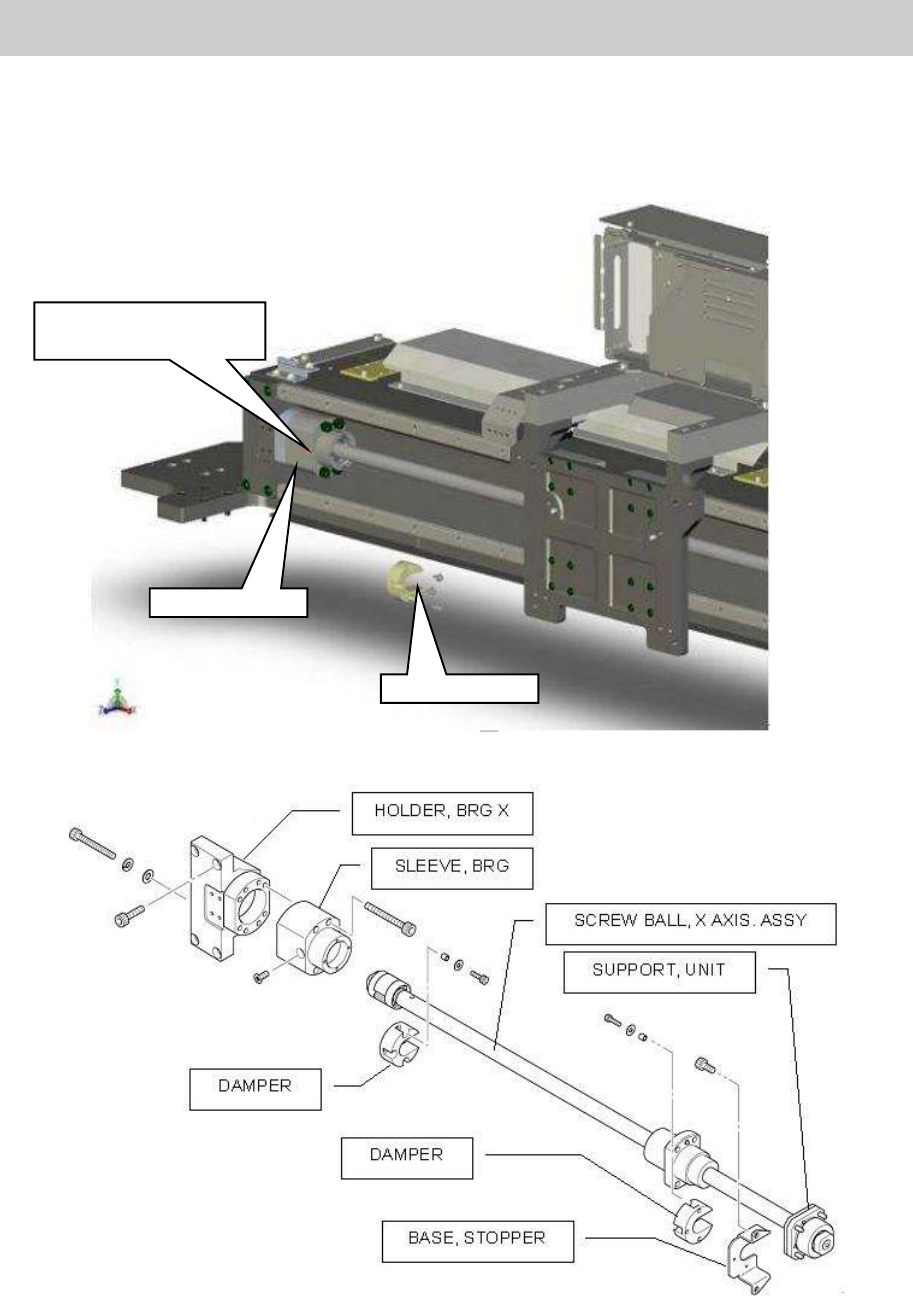
3. Set the SLEEVE BRG in the HOLDER BRG. X AXIS.
When assembling the parts of YGD, YG88, YG100, YG200(L) and YG300 models.
Insert the SLEEVE BRG into the HOLDER BRG. X AXIS and temporarily secure it with the
four fixing bolts (M5*14).
Figure 9
SUPPORT UNIT
HOLDER, MOTOR
X-AXIS MOTOR
Fixing bolts for the
SUPPORT UNIT
(Qty:4)
X-axis ball screw
HOLDER BRG. X
AXIS
Ball Screw of X-Axis
Fixing blolts(M5*14)
(Qty:4)
SLEEVE BRG
Service Engineer
Service Information
SI0802008E-000= YG series: Replacement procedure for ball screws of each axis
10/65
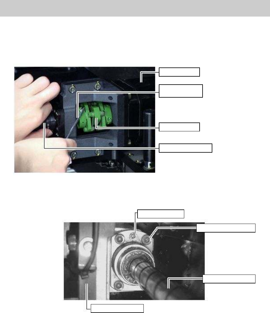
When assembling the parts of YG88R and YG100R models.
1) Move the SLEEVE,BRG to the position where it was and fix it with four bolts. Then
tighten the detent bolt for the SPACER, BRG SET.
2) Fix the DAMPER with three bolts.
Figure 10
Figure 11
DAMPER
SLEEVE, BRG
The detent bolt for the
SPACER, BRG SET
Service Engineer
Service Information
SI0802008E-000= YG series: Replacement procedure for ball screws of each axis
11/65
* The following procedures are common to all the models.
4. Temporarily tighten the coupling.
Temporarily tighten one of the two bolts at the slotted part (No.2 in Figure 1) on the ball screw side
of the coupling.
Figure 12
5. Temporarily fix the screw nut mounted at the center of the ball screw with the four bolts (M5*16/
See No.26 in Figure 1).
Figure 13
Grease nipple
Fixing bolts (Qty: 4)
Ball screw of X-axis
HOLDER, HEAD
X-axis motor
Hex wrench
(Size 3)
Coupling
X-axis ball screw