YAMAHA-YG系列 换螺杆指导书.pdf - 第62页
Service Engineer Service I nformati on SI080 2008 E-000 = YG series: Replacement proc edure for ball screws of each axis 62/65 Figure 88 4. Check the value of the m axim um c urrent com m and. Check the m axim um current…
Service Engineer
Service Information
SI0802008E-000= YG series: Replacement procedure for ball screws of each axis
61/65
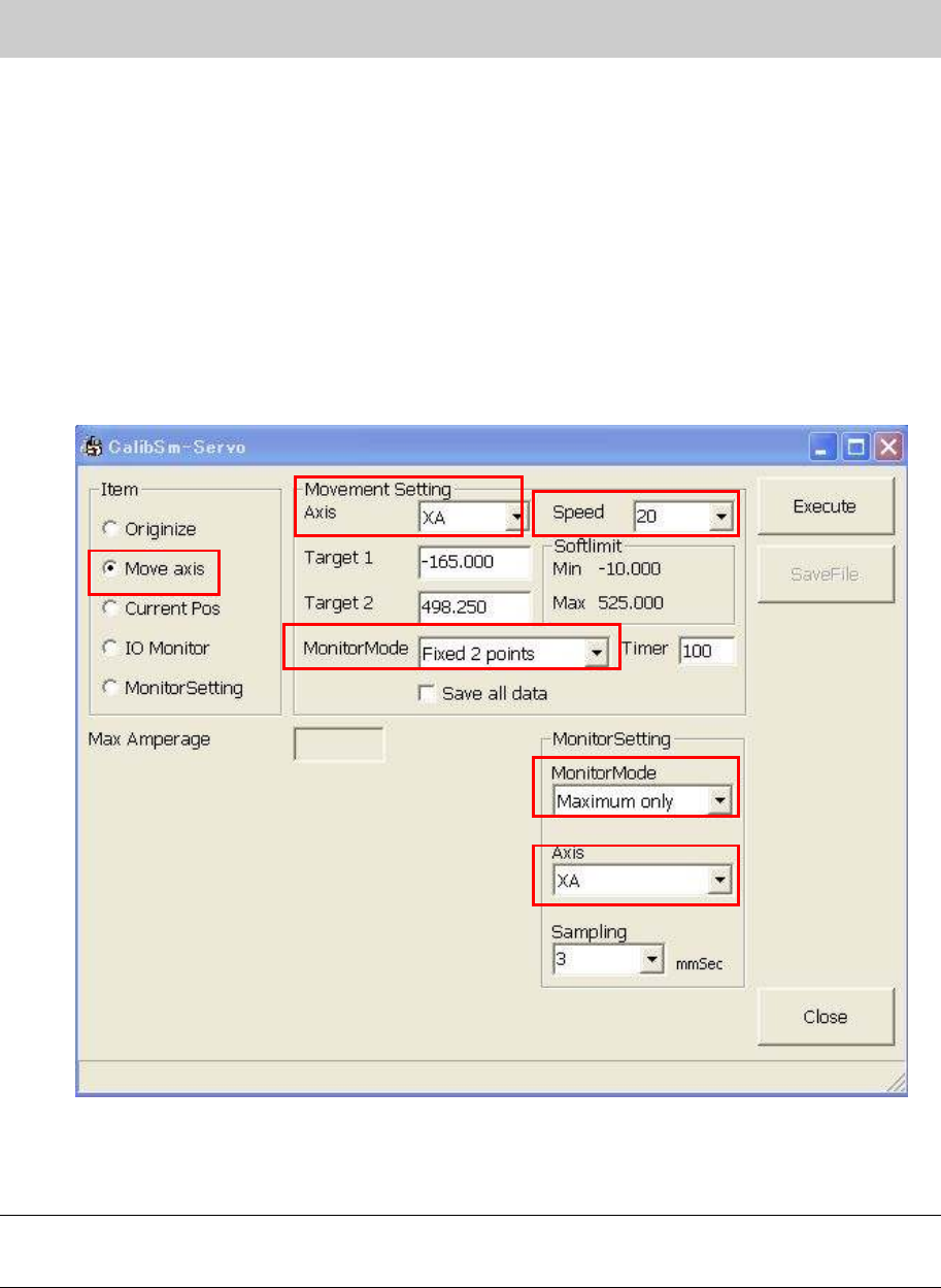
2. Setting for each item.
1) Select “Move axis” from the “Item”.
2) Select the name of the axis to be adjusted from “Axis” item.
3) Select the speed of the axis movement from “Speed”.
Please check the movement of the axis by selecting the low speed before selecting “100%”.
4) Select “Fixed 2 points” or “Random points” from the “MonitorMode” depending on the
situation.
5) “Maximum only” is normally selected from the “Monitor Mode” in the “Monitor Setting”.
6) Select the same axis name selected from the “Axis” item of the “Movement Setting”.
7) Except for the above-mentioned settings, leave the other settings as default.
Figure 87
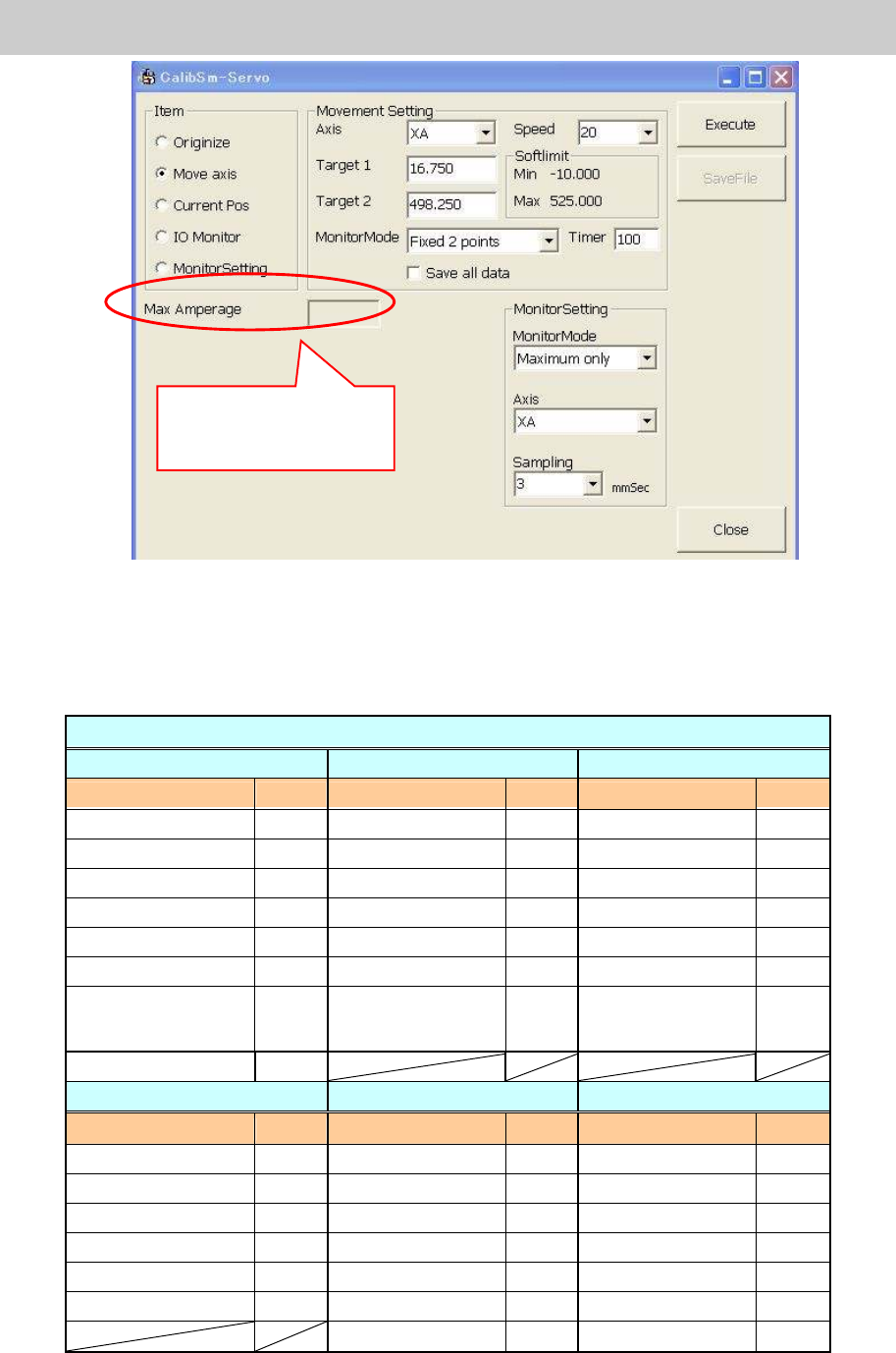
3. Click on the [Execute] button and start measurement.
Caution:
Please do not perform the continuous operation more than 10 minutes, as this servo test is not a
normal operation.
Service Engineer
Service Information
SI0802008E-000= YG series: Replacement procedure for ball screws of each axis
62/65
Figure 88
4. Check the value of the maximum current command.
Check the maximum current command value of the relevant axes referring to Table 5.
If the value exceeds the reference value, please repeat adjustment of the alignment of the
axes until the value falls within specification.
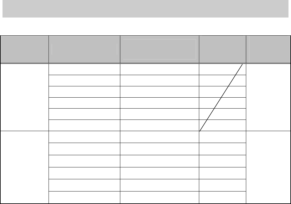
YG series Reference current values of the axes
[YG88, YG88R] [YG100, YG100R] [YG200, YG200L]
Axis name RV [%]
Axis name RV [%]
Axis name RV [%]
X 60 - 90
X 60 - 90
X1,2,3,4 60 - 99
Y 62 - 92
Y 62 - 92
Y1,2 66 - 99
Z1,2,3 - 85
Z1 - 8 22 - 66
Z1,2,3,4 30 - 70
R1,2,3 - 60
R1, 2 13 - 40
R1,2,3,4 3 - 33
W 18 - 53
W 18 - 53
W1,4 13 - 60
PU1 13 - 40
PU1 13 - 40
W2,3 13 - 71
PU2 [YG88]
PU2 [YG88R]
59 - 89
40 - 90
PU2 [YG100]
PU2 [YG100R]
59 - 89
40 - 90
YT1,2 78 - 99
N1,2,3
- 75
[YGD] [i-CUBE II] FF/FD [i-CUBE II] 4M
Axis name RV [%]
Axis name RV [%]
Axis name RV [%]
X
- 85
X
- 85
X
- 85
Y
- 85
Y
- 85
Y
- 85
Z1,2
- 85
Z1,2
- 85
Z1,2,3,4
- 85
R
- 85
R1,2
- 85
R1
- 85
W
- 85
W
- 85
W
- 85
PU
- 90
PU
- 85
PU
- 85
CZ
- 85
CZ
- 85
Table 5
The maximum current
command value is
displayed here.
Service Engineer
Service Information
SI0802008E-000= YG series: Replacement procedure for ball screws of each axis
63/65
5.9. The belt tension specifications
Models Part Number
Conveyor width/
PU specification
Measurement
Part
(1)
Measurement
Part
(2)
KGS-M9210-00X 440mm / Single
KGS-M9210-10X 330mm / Single
KGS -M9210-20X 440mm / Double
KGS -M9210-30X 330mm / Double
KGS -M9210-40X 280mm / Single
-YG88
-YG100
-YGD
KGS -M9210-50X 280mm / Double
240 - 300Hz
KHW-M9210-00X 440mm / Single
60 - 70Hz
KHW-M9210-10X 330mm / Single
60 - 70Hz
KHW-M9210-20X 440mm / Double
140 - 160Hz
KHW-M9210-30X 330mm / Double
140 - 160Hz
KHW-M9210-40X 280mm / Single
60 - 70Hz
-YG88R
-YG100R
KHW-M9210-50X 280mm / Double
140 - 160Hz
290 - 350Hz
Table 6