YAMAHA-YG系列 换螺杆指导书.pdf - 第44页
Service Engineer Service I nformati on SI080 2008 E-000 = YG series: Replacement proc edure for ball screws of each axis 44/65 5. Set the three boards on the convey or. Set the each boad at the entrance, in the center (t…
Service Engineer
Service Information
SI0802008E-000= YG series: Replacement procedure for ball screws of each axis
43/65
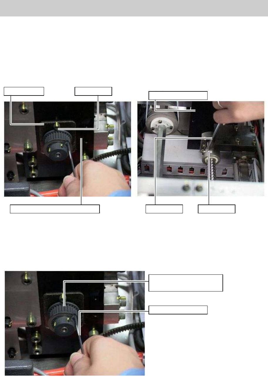
4.3. How to mount the new bearing
1. Put a bearing on the new ball screw on the reference conveyor side, and insert the ball screw into
the conveyor frame.
2. Put a bearing on the driven side of the new ball screw, and temporarily secure the both side of the
bearing with fixing bolts.
Then fix the nut bearing of the ball screw to the conveyor frame.
Figure 60
3. Move the driven-side conveyor frame to the minimum width and fix the bearing on the reference
conveyor side. Then move the conveyor to the maximum width and fix the bearing at the
dead-end side of the bearing.
4. Put the pully on the new ball screw and fix it with two set screws.
Figure 61
Bearing plate
Fixing bolt
Driven-side conveyor
Reference side conveyor stand
Hex wrench
Nut bearing
Pulley for synchronizing the
W-axis movement
Hex wrench (Size 2)
Service Engineer
Service Information
SI0802008E-000= YG series: Replacement procedure for ball screws of each axis
44/65
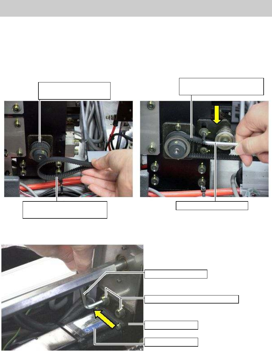
5. Set the three boards on the conveyor.
Set the each boad at the entrance, in the center (the set position) and the exit of the conveyor,
and rotate the pulley on the right and left side so that the boards touch the board guide.
6. Hook the timing belt around each pulley.
Temporarily remove the belt from the pulley, and rotate the pully to make the conveyors parallel to
each other. Then engage the belt and the pulley again, tighten the belt properly and fix the belt
tensioner.
Figure 62
7. Hook the belt around the pulleys on both the W-axis motor side and the ball screw side.
8. Tighten the W-axis belt and temporarily fix the motor.
Figure 63
9. Check and adjust the machine reference of the W-axis.
Please refer to “5.4.2. Adjust the machine reference” for the method.
Adjust the engage point of the gears of the belt and the pulley so that the machine reference falls
within 50 +- 15%.
10. Adjust the belt tension of the W-axis belt.
Loosen the bolts that fix the motor to adjust the belt tension to be fallen within the specification
350 – 450 Hz by using the tension gauge. Then fix the bolts.
Pulley for synchronizing
the W-axis movement
Timing belt for synchronizing
the W-axis movement
Timing belt for synchronizing
the W-axis movement
Hex wrench (Size 4)
Hex wrench (Size 4)
Bolts for fixing the motor (M5)
Motor plate
W-axis motor

Service Engineer
Service Information
SI0802008E-000= YG series: Replacement procedure for ball screws of each axis
45/65
4.4. Adjustment after replacing the ball screw
The coordinates of the machine deviate due to the replacement of the parts. Therefore, some works
need to be done in order to restore the coordinates in the simple method.
Caution:
Please make sure to do the necessary work before replacement. Otherwise, you will need to perform
all the adjustment, which requires a great deal of time later on.
<Works to be done>
• Adjust the machine reference and the initial position of the W-axis.
• Check the peak current (With the “Servo utility”).
* Please refer to the relevant section in “5. Adjustment”.
Check if the bolts are tightened properly
1. Press the [Emergency stop] button and check the surrounding area for safety.
2. Check the bolts removed for replacement or loosened are tightened properly.
Check if the bolts are tightened with the appropriate hex wrench and make a mark on the
bolts with the marker pen.
Other items to be checked and done
1. Check if there are any tools used for replacement left in the machine.
2. Check if there are any pieces of cut off cable tie left in the machine.
3. Make sure that all the harnesses are secured properly, and no axes interfere with anything
when they move.
Caution:
Please do not use an air gun for cleaning inside the machine. The blown away dusts may stick to the
moving parts of the axes, which causes the serious problem to the machine.
4. Get ready for the production activity
Put back all the removed parts such as feeders and other supplying equipments to the
original position.