YAMAHA-YG系列 换螺杆指导书.pdf - 第49页
Service Engineer Service I nformati on SI080 2008 E-000 = YG series: Replacement proc edure for ball screws of each axis 49/65 5.3. Useful f unctions (Help) How to use th e help function of the “Adjustment Utilit…
Service Engineer
Service Information
SI0802008E-000= YG series: Replacement procedure for ball screws of each axis
48/65
2. Select the mode for adjustment. (If it is set in “VmSpec”, it does not have to be changed.)
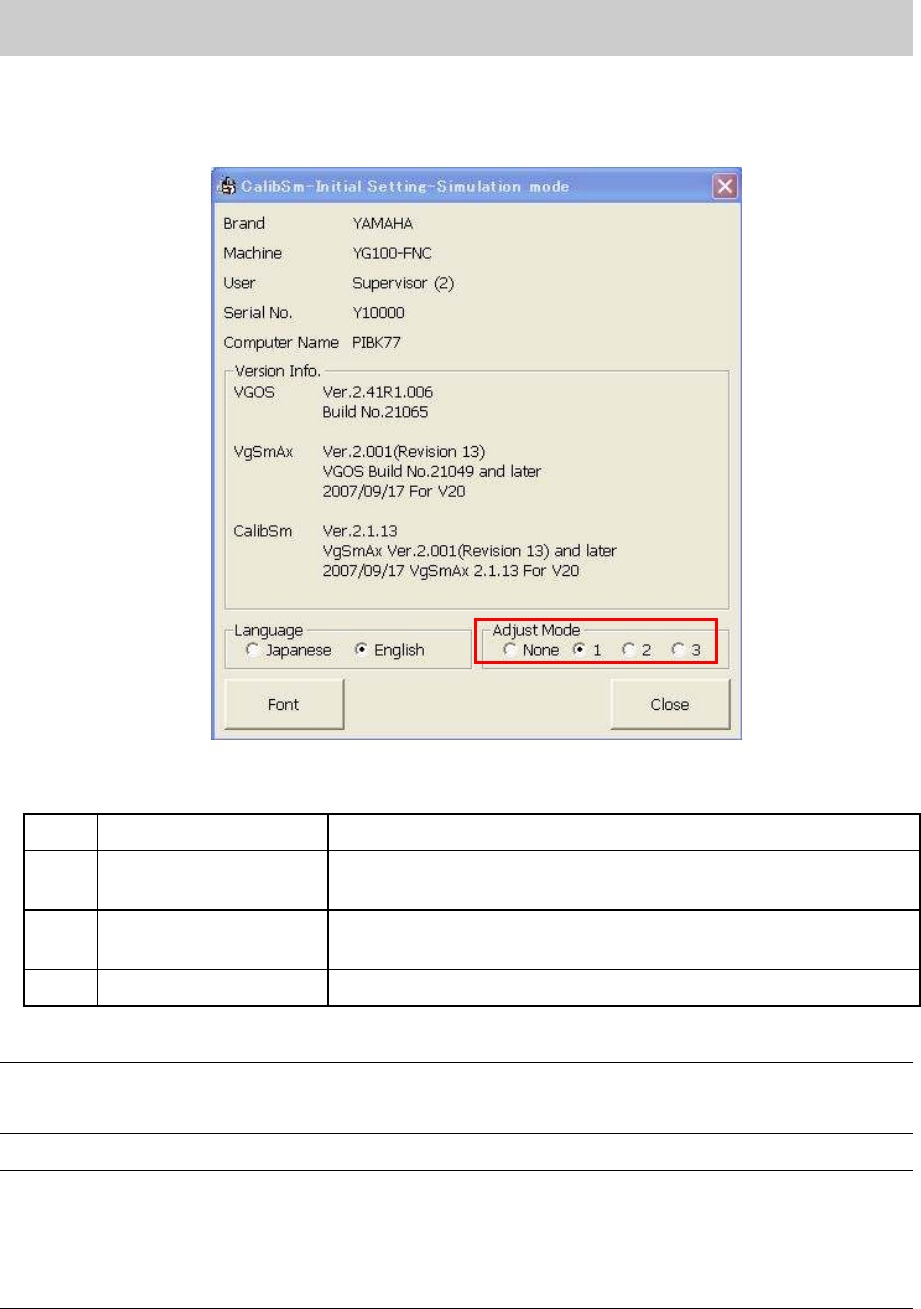
Select the radio button “1” from the “Adjust Mode”.
<Initial setting dialog>
Figure 68
<Adjust Mode>
None
Adjust Mode -None Used for Normal production.
1 Adjust Mode 1
Used for adjustment of mounting CHIP components in ACP and
FAMF adjustment.
2 Adjust Mode 2
Used for adjustments of Lead components recognition,
binarization (Black and white) and inversion in FAMF.
3 Adjust Mode 3 Not available
Table 1
Note:
The setting can be switched easily by selecting the radio button of the “Adjust Mode”. However, when
the “Adjustment Utility” is closed, the setting becomes invalid.
Caution:
When performing “ACP adjustment” by using the new ACP board and the CHIP component, please
make sure to switch the adjust mode to “1”.
If the radio button “1” is not selected, when a pick up error occurs, the retry of the head that caused the
error may not be performed. In this case, the head to be adjusted and other head are exchanged and
compensation value cannot be obtained correctly.
Service Engineer
Service Information
SI0802008E-000= YG series: Replacement procedure for ball screws of each axis
49/65
5.3. Useful functions (Help)
How to use the help function of the “Adjustment Utility” (Calib Sm)
The “Adjustment Utility” has a useful “Help” function. In the “Help” utility, simple procedures for each
adjustment is described.
While the utility is running, the “Help” screen is displayed whenever necessary, just by pressing the
[F1] key.
<Example>
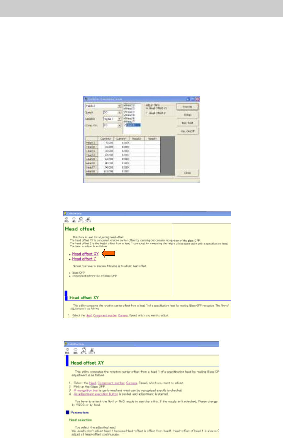
When you need to know how to adjust the “Head Offset”.
Figure 69
1. Press the [F1] key.
The “Help” screen is displayed. Select the “Head Offset XY” in the “Head Offset” item.
Figure 70
2. The procedure for “Head Offset XY” is displayed. Please perform adjustment according to the
procedure.
Figure 71
Service Engineer
Service Information
SI0802008E-000= YG series: Replacement procedure for ball screws of each axis
50/65
5.4. Machine reference for each axis
5.4.1. Check the machine reference for each axis
1. Release the [Emergency stop] button.
Caution:
Please make sure that all the tools and components in the machine are removed before releasing the
“Emergency Stop” button.
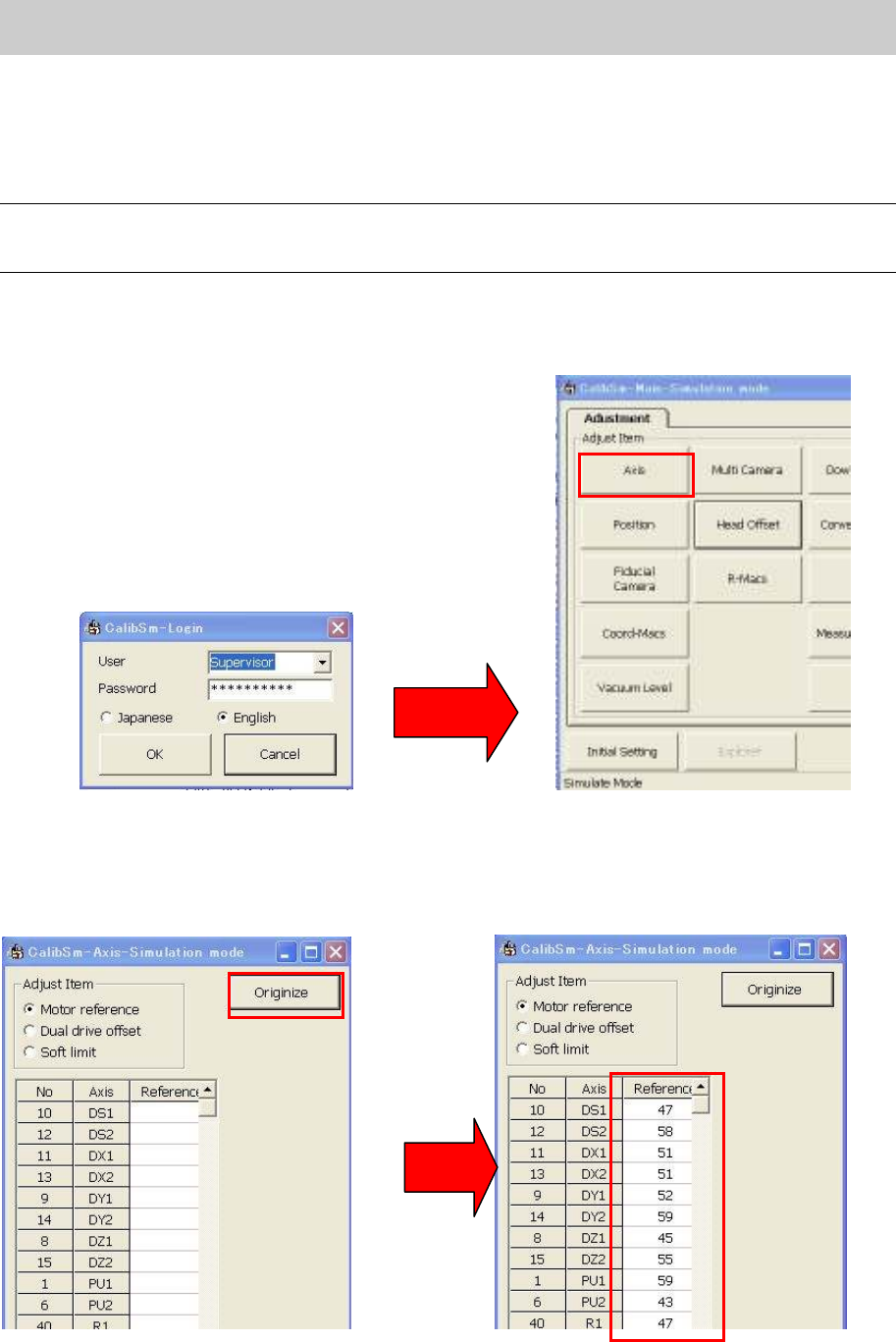
2. Click on the [Utilities] button on the “Setup” screen to activate “Calib Sm”.
Please login as “Supervisor”.
3. Click on the [Axis] button.
Figure 72
4. Click on the [Originize] button.
5. The data of the machine reference for each axis are displayed in the “Reference” column. Please
note down the data.
Figure 73