YAMAHA-YG系列 换螺杆指导书.pdf - 第51页
Service Engineer Service I nformati on SI080 2008 E-000 = YG series: Replacement proc edure for ball screws of each axis 51/65 5.4.2. A djust the machine reference 1. Release the [Emergency Stop] button. 2. Click on the …
Service Engineer
Service Information
SI0802008E-000= YG series: Replacement procedure for ball screws of each axis
50/65
5.4. Machine reference for each axis
5.4.1. Check the machine reference for each axis
1. Release the [Emergency stop] button.
Caution:
Please make sure that all the tools and components in the machine are removed before releasing the
“Emergency Stop” button.
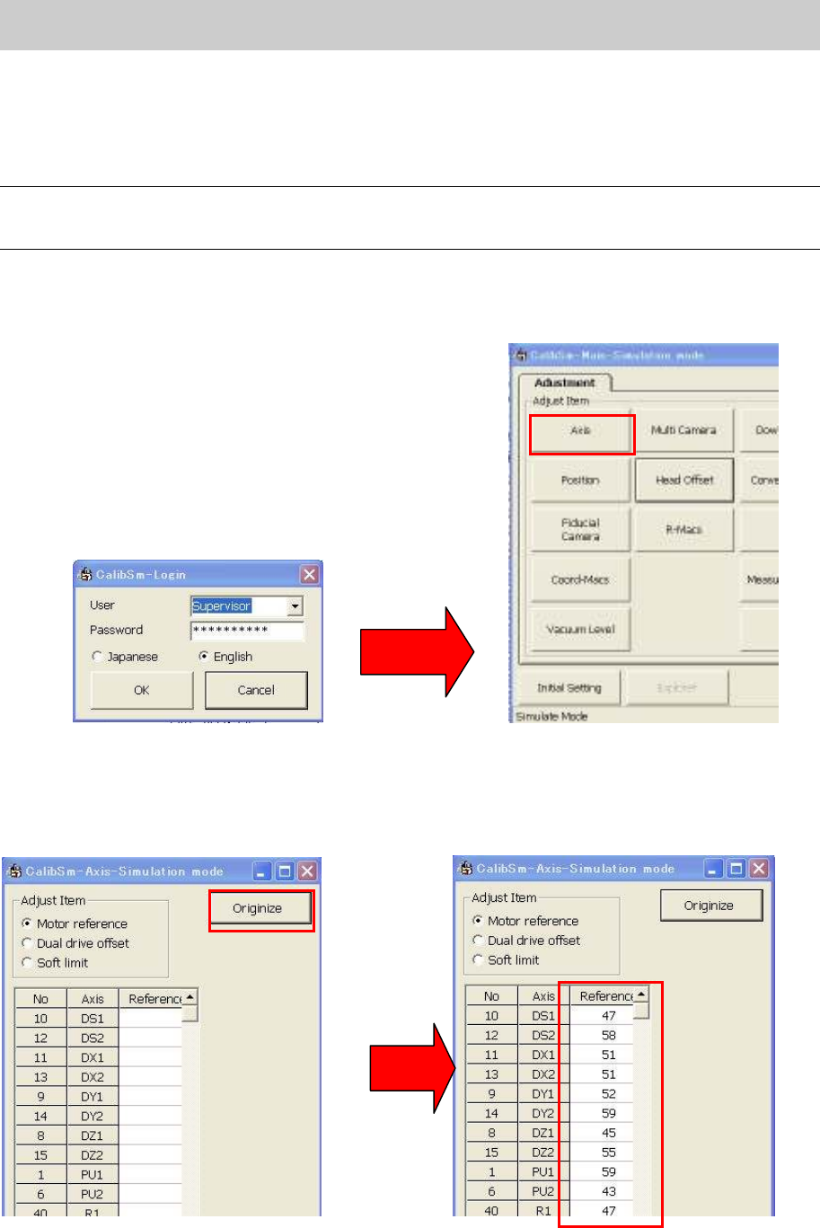
2. Click on the [Utilities] button on the “Setup” screen to activate “Calib Sm”.
Please login as “Supervisor”.
3. Click on the [Axis] button.
Figure 72
4. Click on the [Originize] button.
5. The data of the machine reference for each axis are displayed in the “Reference” column. Please
note down the data.
Figure 73
Service Engineer
Service Information
SI0802008E-000= YG series: Replacement procedure for ball screws of each axis
51/65
5.4.2. Adjust the machine reference
1. Release the [Emergency Stop] button.
2. Click on the [Utilities] button on the “Setup” screen to activate “Calib Sm”.
3. Click on the [Axis] button on the Main menu screen.
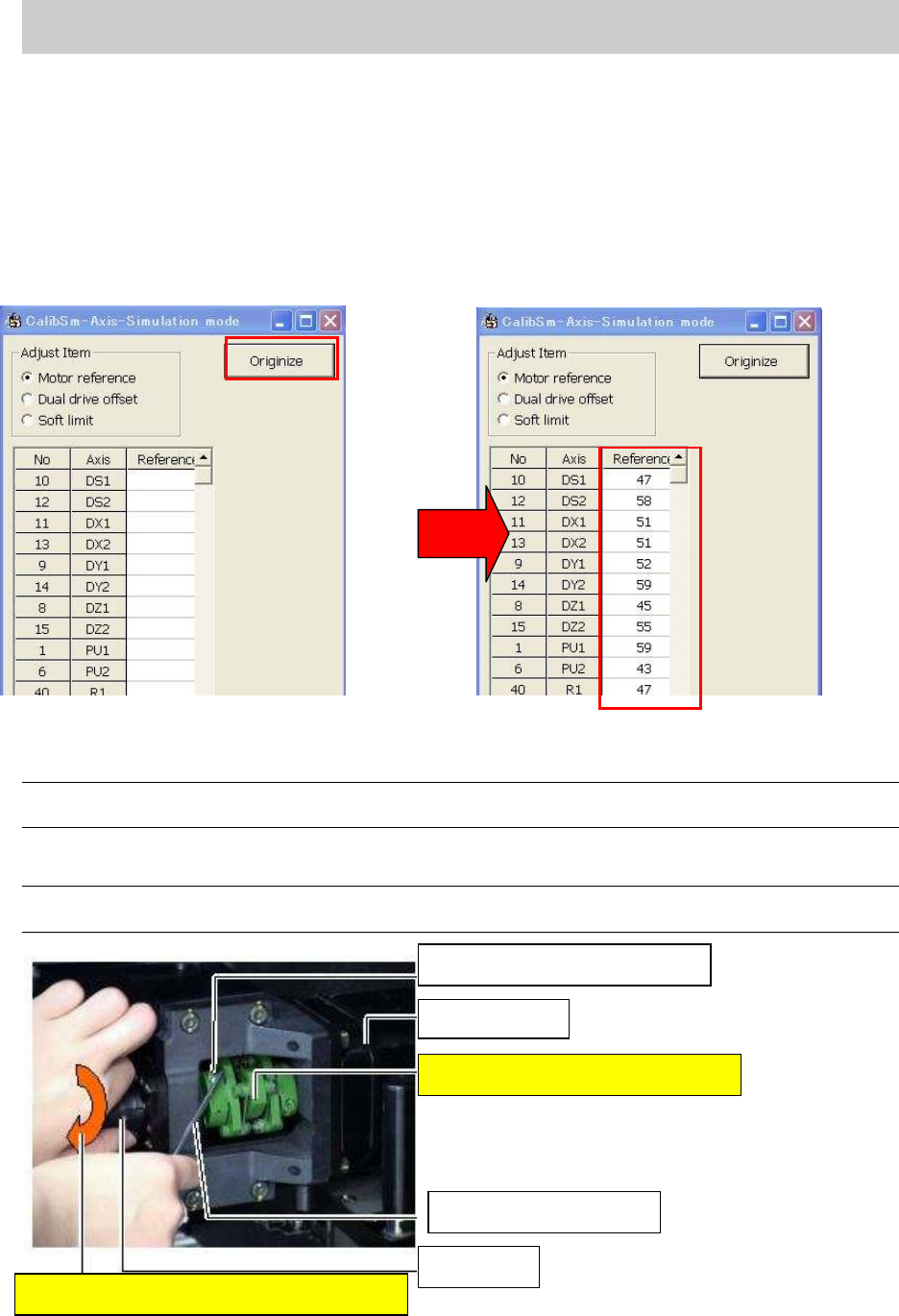
4. Click on the [Originize] button on the “Axis” screen.
5. The data of the machine reference for each axis are displayed in the “Reference” column after the
Return-to-origin operation. Please check the data.
Figure 74
6. Loosen the coupling and adjust the axis position to the reference coordinate position.
Note:
Please adjust the position within the machine reference standard value: 50+-10% (45-55).
How to adjust the X-axis (YG100 model)
Caution:
When loosening the coupling of the motor, please loosen the one on the ball screw side.
Figure 75
The fixing bolt for the coupling
X-axis motor
The coupling must not be moved.
Hex wrench (Size 3)
Ball screw
Rotate the ball screw to adjust the position
Service Engineer
Service Information
SI0802008E-000= YG series: Replacement procedure for ball screws of each axis
52/65
5.4.3. Check and adjust the Y2-axis dual offset
Please make sure to check the offset balance between the Y1 motor and the Y2 motor as it may be
disrupted due to the replacement of the Y-axis motor.
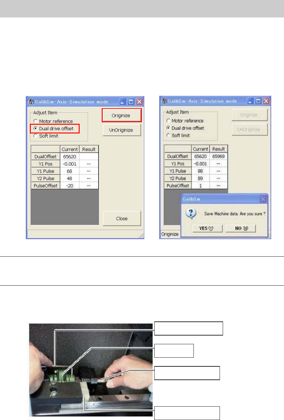
1. Select “Dual drive offset” from the “Adjust Item” and click on the [Originize] button.
2. Check the value of the Y2-axis dual offset.
The standard value of “Dual Offset”: 63700 – 64300
Please repeat the procedure 1) through 3) until the value falls within the specification.
Figure 76
Note:
If the value does not fall within the specification (63700-64300) of the Dual Offset, please click on the
“No” button without saving the data. If the data is saved accidentally, please click on the [UnOriginize]
button.
3. Adjust the Dual Offset of the Y2-axis.
Loosen the two fixing bolts on the ball screw side with a hex wrench (Size 4), and rotate the ball
screw little by little in order to adjust the position to the specified value while securing the coupling.
Figure 77
Hex wrench (Size 4)
Coupling
Y2-axis ball screw
Mechanical stopper