YAMAHA-YG系列 换螺杆指导书.pdf - 第33页
Service Engineer Service I nformati on SI080 2008 E-000 = YG series: Replacement proc edure for ball screws of each axis 33/65 Note: Please refer to the specificaition of the belt tension for each m odel at the end of th…
Service Engineer
Service Information
SI0802008E-000= YG series: Replacement procedure for ball screws of each axis
32/65
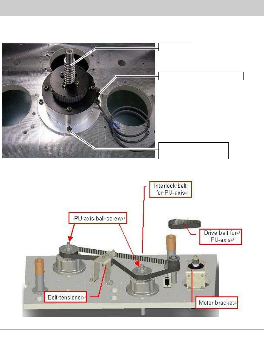
3. Set the axis unit on the base and fix it to the base with four bolts.
[YG88 & YG100]
Figure 43
[YG88R & YG100R]
Figure 44
Note:
YG88R and YG100R machines have two ball screws. As the ball screws are driven via inter midiate
shaft, two types of belts are used. One is for driving the ball screws and the other is for interlocking the
movement of the ball screws.
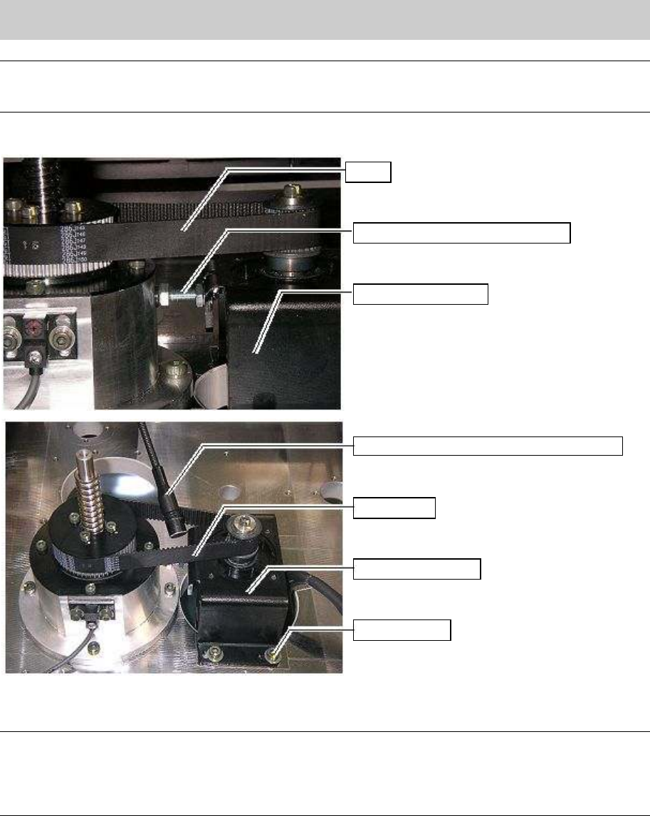
4. Adjust the belt tension.
Put the belt arount the pulley of the unit and the pully of the motor. (put the belt so that the letters
written on the belt can be read from your side.)
Fully tighten the bolts of the motor bracket while adjusting the tension of the belt.
Connect the connector of the origin sensor and turn on the machine, then perform
Return-to-origin.
Ball screw
Origin sensor for PU-axis
Bolts for fixing the
bearing housing (Qty:4)
Service Engineer
Service Information
SI0802008E-000= YG series: Replacement procedure for ball screws of each axis
33/65
Note:
Please refer to the specificaition of the belt tension for each model at the end of this document.
The specification of the tension for YG88 and YG100 when using the tension gauge is 240 - 300 Hz.
[YG88 &YG100]
Figure 45
[YG88R &YG100R]
Note:
YG88R and YG100R machines have two ball screws. As the ball screws are driven via inter midiate
shaft, two types of belts are used. One is for driving the ball screws and the other is for interlocking the
movement of the ball screws.
Please refer to “5.9. The belt tension specifications” for the values of the belt tension.
5. Connect the motor harness of the PU-Axis and the connector of the origin sensor.
6. Turn on the machine.
7. Press the [Emergency stop] button.
Belt
Bolt for adjusting the belt tension
Motor bracket
Microphone of the tension gauge
Belt
Motor bracket
Fixing bolt
Service Engineer
Service Information
SI0802008E-000= YG series: Replacement procedure for ball screws of each axis
34/65
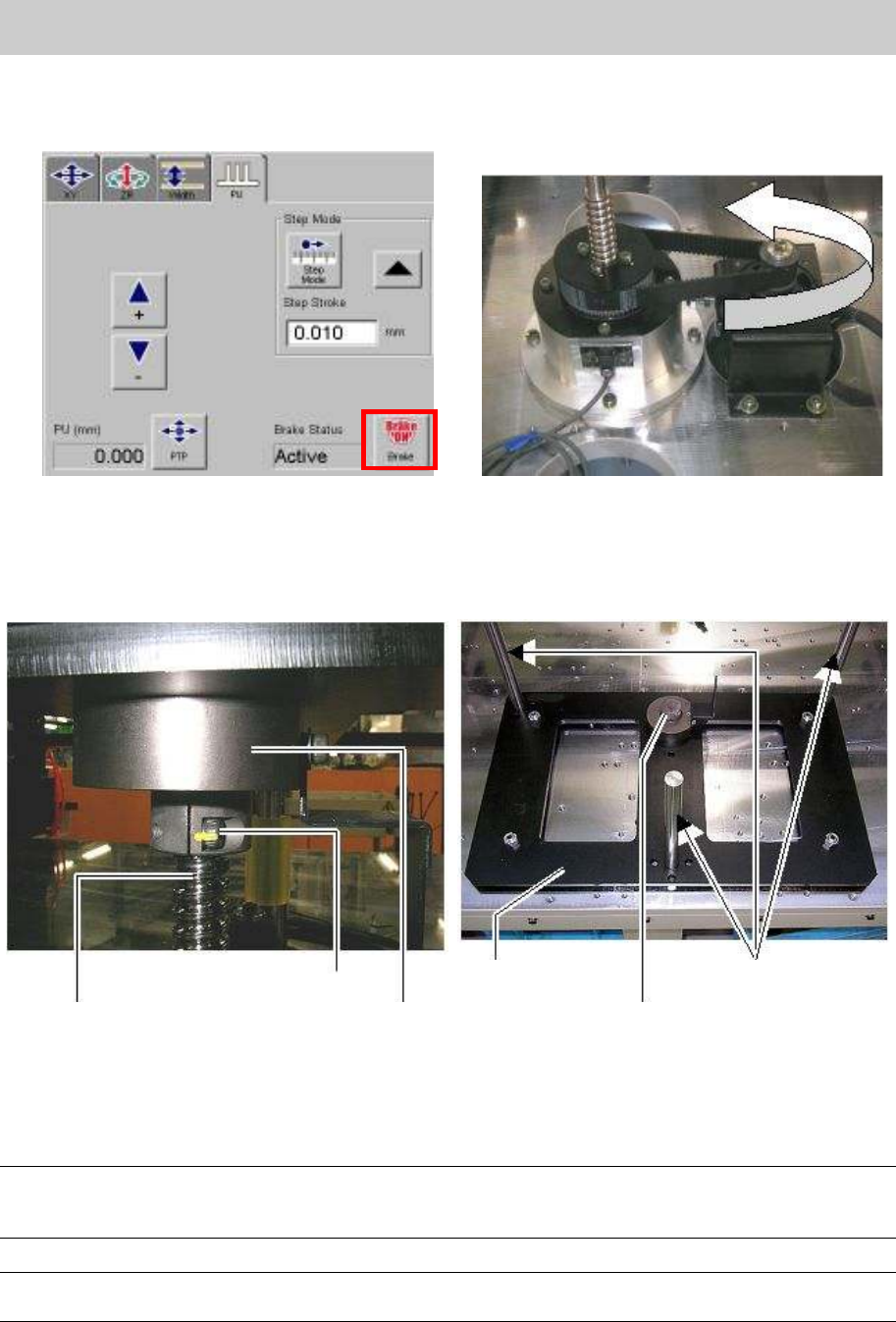
8. Click on the [Unit] button and select “Conveyor” tab, then click on the [Axis] button and select the
[PU] tab. Click on the [Brake] button at the lower right of the screen in order to release the brake.
Then check if the ball screw moves up and down smoothly while moving the belt by hand.
Figure 46
9. Place the damper on the ball bush, and insert the three shafts of the ball bush into the holes on
the removed stay, and push the joint part on the stay downwards, then tighten the two bolts where
the ball screw is inserted.
Figure 47
10. Release the [Emergency stop] button and perform Return-to-origin.
11. Adjust the machine reference of the PU-axis by fine-adjusting the position of the origin dog.
Caution:
Before adjusting the position of the limit dog mechanically for adjusting the machine reference, please
make sure to press the [Emergency dtop] button and check the surrounding area for safety.
Note
The standard value of the machine reference: Within 50 +- 10% (45-55)
Ball screw
Fixing bolt
Joint
Stay
Joint
Shaft of the ball bush