YAMAHA-YG系列 换螺杆指导书.pdf - 第15页
Service Engineer Service I nformati on SI080 2008 E-000 = YG series: Replacement proc edure for ball screws of each axis 15/65 2.2. How to r emove the ball screw of Y1,2-axis Caution: As som e rem oved parts may contain …

Service Engineer
Service Information
SI0802008E-000= YG series: Replacement procedure for ball screws of each axis
14/65
2. How to replace a ball screw of Y1,2-axis
Required tools
- Phillips-head screw driver (Standard type)
- Hex wrench set
- Special T-shape hex wrench (Size 5) or ratchet wrench set
- Nipper
- Some cable ties (150mm, 250mm)
- Marker pen (Used after checking if the screws are tightened properly)
- New ball screw for Y1,2-axis (Sub-Assy. Part)
2.1. Work to be done before replacement
The coordinates of the machine deviate due to the replacement of the parts. Therefore, some works
need to be done in order to restore the coordinates in the simple method.
Also, in case the ball screw is broken or the problem such as seizure occurs, the works before the
replacement cannot be performed and various adjustments need to be performed.
Caution:
Please make sure to do the necessary work before replacement. Otherwise, you will need to perform
all the adjustment, which requires a great deal of time later on.
<Works to be done>
- Check the machine reference of each axis
- Set the reference coordinate before replacement of the ball screw.
* Please refer to the relevant section in “5. Adjustment”.
Service Engineer
Service Information
SI0802008E-000= YG series: Replacement procedure for ball screws of each axis
15/65
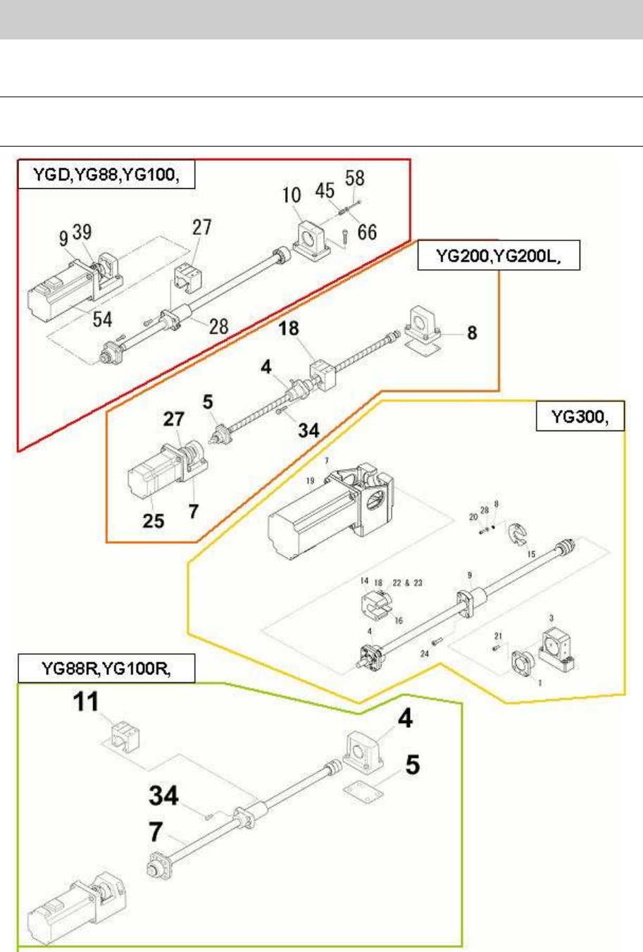
2.2. How to remove the ball screw of Y1,2-axis
Caution:
As some removed parts may contain shims, please be careful not to lose them. Also, please note
down the places where the shims were set.
Figure 16
Service Engineer
Service Information
SI0802008E-000= YG series: Replacement procedure for ball screws of each axis
16/65
When removing the ball screw of YGD, YG88 and YG100 models.
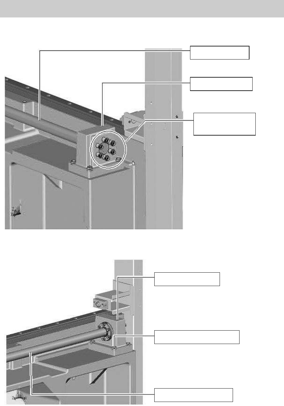
1. Remove the six bolts (M4*30) of the coil springs that pull the ball screw.
Figure 17
2. Remove the four bolts that fix the HOLDER BRG Y (No.10 in Figure 16).
Figure 18
Ball screw of Y-axis
HOLDER, BRG. Y
Bolts for the coil
springs of the
Y-axis ball screw
HOLDER, BRG. Y
Bolts to fix the holder (Qty:4)
The ball screw of Y-axis